
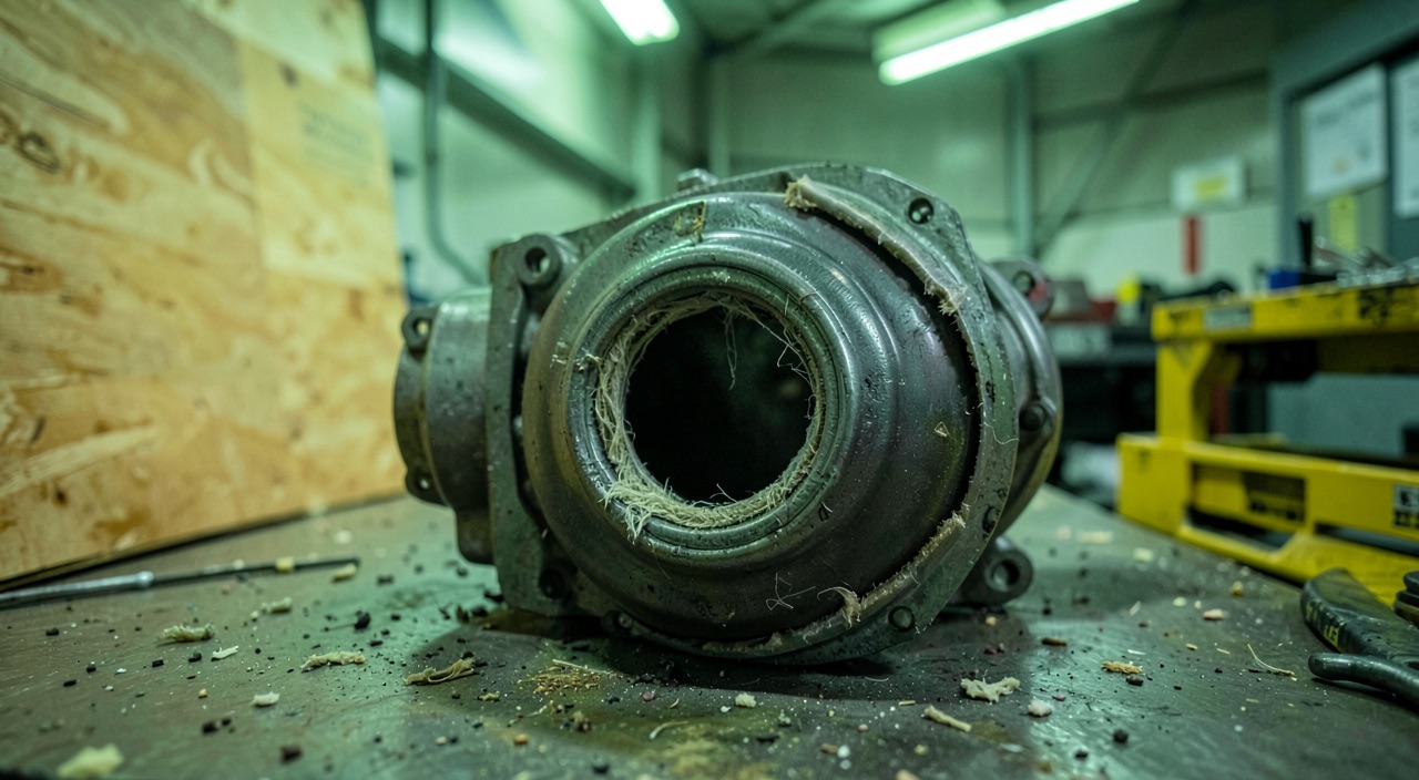
The casing held: that’s what the control room retains when the pyrotechnic charge severed the blade root at the maximum authorized speed. Yet, the question that interests the operator is not that one. This unique test, on a new engine, with a blade chosen because it is the most unfavorable, demonstrates a very specific property; and it leaves out of its scope almost everything that, in service, separates a lost engine from a lost aircraft.
What the test stages, and nothing else
The protocol is known and brutal. Complete engine installed on the test bench, throttle in takeoff position, rotor at maximum permitted speed, a charge severs the blade as close as possible to its outermost attachment. The maximum possible mass is thus released, at the maximum possible peripheral speed. The expected results are summarized in a few lines: no dangerous fragment must cross the casing, no fire must persist, the engine attachments must remain capable of retaining the engine, and the crew must retain the possibility of shutting it down.
The test does not stop at the impact, and that’s the first thing one forgets when summarizing it. The engine must continue to run for a prescribed duration at the initial speed, before the throttle is brought back and the machine is kept at idle for a certain time. This part does not demonstrate containment: it demonstrates that the structure survives the imbalance that the containment has just created.
The blade is not chosen at random. It is the one that, after an analysis covering the entire rotor, stresses the casing the most severely: a combination of mass, radius, stiffness, and angle of attack of the fragment. The entire value of the demonstration rests on this choice, since the test is unique. There is no population, no dispersion, no statistical margin: a single event, successful or not. The robustness comes from a chain of upstream analyses, subsequently calibrated on the measurement, and not from repetition.
The test proves that the engine casing can hold a blade fragment under extreme conditions, but it doesn’t test everything that happens after. The engine must keep running to show the structure can handle the imbalance, and the blade chosen is the worst-case scenario to ensure the test is as tough as possible.
On a test of a CFM LEAP-1B engine, a fan blade was severed at 15,000 RPM (maximum takeoff speed) on a test bench. The casing held, and the engine continued running for 30 minutes to prove it could handle the imbalance. The blade was chosen as the heaviest and most rigid one to ensure the test was as challenging as possible.
Retaining is not stopping
The image of the passive shield is false. The casing does not stop the blade abruptly: it makes it tilt, accompanies it, drags it over a significant angular sector by dissipating energy through plastic deformation, friction, and secondary fragmentation. The difference between a casing that contains and a casing that is pierced lies less in the thickness of the metal than in the incidence of the fragment at first contact and in the way it then tilts.
Two families coexist. The thick metal casing absorbs by local plastification: it stretches, bulges, absorbs. The thin casing lined with a fiber winding works entirely differently: the sheet guides and cuts, the layer absorbs the energy as a membrane, stretching over a large circumferential length. The latter is lighter for equal retained energy, but it tolerates much less deviation in the impact geometry, and a layer that has worked cannot be repaired: the assembly must be replaced.
The failure mode to be feared is not always a clear perforation. It is more often a shearing rupture at the level of a flange, a tear that propagates axially, or an ejection forward through the air intake, where the casing no longer has any thickness to offer. The radial bulging is also measured, because a casing that contains but then touches the nacelle or a duct only shifts the problem.
The imbalance is the second half of the test
A missing blade on a large-diameter fan is an imbalance without common measure with the usual balancing tolerances. The alternating forces that result rise from the bearings to the casing, from the casing to the pylon, from the pylon to the wing. They do not disappear when the engine is shut down: the rotor continues to turn in windmilling, driven by the airflow, and the imbalance with it.
Two regimes must therefore be covered. The short duration at high speed, immediately after the release, which is that of the test. And the prolonged windmilling, which lasts as long as the diversion and which, in practice, sizes the fatigue strength of the attachments as well as the dynamic response of the wing. This second phase is not demonstrated by a several-hour test on the bench: it is justified by calculation, calibrated on the forces measured during the rupture test.
Hence a device widespread on recent large-fan architectures: a bearing support deliberately calibrated to break beyond a certain force. By yielding, it frees the shaft, which begins to rotate around an axis closer to its new center of inertia. The transmitted force drops. The price to pay is assumed and documented: contacts between rotating and fixed parts, wear of the seals, definitive loss of the engine.
Where the demonstration stops: the high-energy parts
No reasonable casing retains a disk sector, a drum, or a shaft fragment. The energy is of a different order, and the mass of armor required would make an engine that does not fly. For these parts, the compliance logic shifts: one no longer demonstrates that an event is survivable, one demonstrates that it is extremely improbable.
This translates into an entirely different device. Material definition and controlled inclusion purity, systematic non-destructive testing during manufacturing, individual traceability, fatigue life limit expressed in cycles and not in hours, and for some parts an approach to damage tolerance that assumes an initial defect and imposes the inspection interval that goes with it. Safety no longer comes from a structure, it comes from a management system.
This shift explains the difference in treatment during investigations. A contained blade fragment questions the casing; a released disk fragment questions the part’s life cycle, from casting to the last workshop visit. These are neither the same interlocutors nor the same operational consequences.
| Released part | Énergie relative | Main means of compliance | What remains to be monitored in service |
|---|---|---|---|
| Fan blade | High: maximum radius and mass | Bench blade-off test on the most unfavourable blade, followed by a period of unbalanced running | Leading-edge erosion and damage, blending criteria, vibration monitoring |
| Compressor or turbine blade | Lower per blade, but hot and often multiple | Partial tests and correlated analysis, cases sized by calculation | Secondary effects of ingestion, creep and deposits, borescope inspections |
| Disc, drum, hub, shaft | Beyond the reach of any realistic containment | No containment demonstration: integrity proven by design, material inspection and life limits | Strict compliance with cyclic life limits, traceability, follow-up of any overspeed event |
What the aircraft must withstand alone
Since the fragment will exit, the aircraft level takes over with a different objective: to minimize the consequences. The reasoning is based on a conventional trajectory model. A large fragment is assumed to leave in a narrow sector around the plane of rotation; intermediate and small fragments are assumed to leave in a wider cone, forward and aft. These are not observed physical probabilities, they are design envelopes.
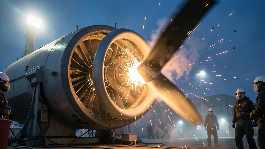
Concrete installation rules are derived from this: not to route two redundant hydraulic circuits on the same side of the plane of rotation, to move essential flight controls away, to protect or move fuel tanks, to accept that part of the cell will be perforated and to verify that no single fragment deprives the crew of everything. This is why an apparently innocuous modification to the routing of a harness can be part of a heavy installation file.
The reasoning changes scale again as soon as one leaves the transport turbofan. On a turboprop, there is no equivalent of the fan casing: a released propeller blade is retained by nothing, and the protection is entirely at the aircraft level—position of the propeller plane relative to the cabin and essential circuits, criteria for admissible damage on the blades, monitoring of impacts and repairs. The auxiliary power unit follows a similar logic: it often runs on the ground, doors open, in immediate proximity to the rear structure and personnel, so its burst zone weighs more on the installation than the strength of its own casing. Same mechanics, three different responses depending on what the architecture allows to be retained.
The trap. Treating a successful containment as a benign event. The scope of the demonstration stops at the casing: the air intake, the fan cowls, and the thrust reverser are not covered by the same test. A casing that perfectly retains may be followed by a disintegration of the air intake, with projection of structure toward the fuselage, impact on a window, and depressurization. This is added to an asymmetric drag much greater than that of a simple engine failure, hence a need for directional control that has nothing to do with the simulator exercise.
The right reflex. After a blade rupture, read the indications as clues, never as criteria. An unbalanced rotor continues to windmill: a non-zero speed proves nothing about the state of the engine. A drop in the vibration indication also proves nothing: it accompanies both the deceleration of the rotor and an additional loss of material that has fortuitously rebalanced the wheel. The useful sequence remains the severe engine damage procedure carried out to the end, without any attempt at relight, with a landing decision made by integrating the actual drag and not the tabulated drag.
From the test bench to the line: what doesn’t resemble each other
The test is performed on a new engine, with blades at production standard, on the ground, without relative wind, without wings, and only once. In service, the blades have been eroded, impacted, reprofiled, sometimes repaired; the blade roots have worked in their slots, the inter-blade dampers have taken up play, the coatings have aged. The blade that breaks in service is not the one that was tested, and its fracture geometry may differ.
This is precisely why the real line of defense is not the casing but the inspection program. Admissible damage criteria on the leading edges, authorized depth and length of repairs, checks after ingestion, monitoring of balancing and vibration trends: each of these elements exists to keep the fleet within the assumptions that made the test representative. Letting them drift is to silently invalidate the demonstration.
What to go check in your own documentation
Three checks are worth the detour, and they take no more than an hour. In the flight manual and abnormal procedures, reread the exact wording of the severe engine damage procedure, and what it says—or does not say—about relight and windmilling duration. In the engine documentation, identify the inspection scope triggered by a high vibration event: it almost always goes beyond the fan alone and goes up to the attachments. In the operations file, finally, verify the coherence between the justified windmilling duration and the maximum diversion time retained, especially for extended-range operations.
The gray area that remains is the nacelle and thrust reverser. Its strength after a blade rupture is the subject of an installation file specific to each aircraft-engine pair, with its own assumptions, and it is rarely exposed in the operating documents. For those preparing a type qualification, a certification presentation, or a technical interview, being able to state without hesitation what the test demonstrates and what it leaves to analysis is a real differentiator; it is also the subject of the system knowledge modules offered on formations.fl330.com.
These references have only a value of perspective: the applicable certification specifications, the current airworthiness directives, and the approved operator documentation prevail in all circumstances over the present article.


Leave a Reply
You must be logged in to post a comment.