
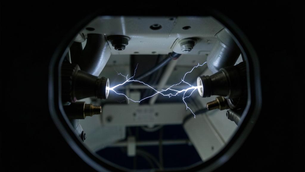
A high-voltage connector that behaves perfectly on the bench can start eroding itself an hour into cruise, and nothing on the flight deck will say so. The reason is not the solid insulation and not a build defect. It is the air: at cruise altitude there is roughly a fifth as much of it in the gap, and thin air is a worse insulator than thick air. Every design decision about aerospace high-voltage cabling — spacing, potting, screening, sealing, connector geometry — is downstream of that single fact, and so is most of what goes wrong.
What actually breaks down is the air
Start with the thing that is easy to get backwards. When a high-voltage installation fails electrically, the first thing to give way is almost never the solid insulation. Polymers, ceramics and impregnated papers withstand field strengths an order of magnitude above what air can take. The weak dielectric in the assembly is the gas surrounding it.
Dry air at sea level breaks down at roughly three kilovolts per millimetre, and that figure is the whole basis of conventional clearance design: keep enough millimetres between conductors at different potentials and the air will not ionise. What makes aviation different from a factory floor is that the figure is not a constant. It scales with gas density, because breakdown is an avalanche — a free electron accelerated by the field must strike a molecule hard enough to liberate another, and then those two must do the same. Fewer molecules per unit volume means longer free paths, more energy gained between collisions, and an avalanche starting at a lower applied voltage.
So a gap that holds off a kilovolt on the ramp holds off substantially less at forty thousand feet. Nothing changed in the hardware. The insulator between the conductors simply got thinner.
Paschen’s law, and why a gap can be too small as well as too big
The classical description is Paschen’s law, whose useful content is that breakdown voltage depends not on pressure or gap separately but on their product. Plot one against the other and you get a curve with a minimum. To the right of it — normal pressures, ordinary gaps — breakdown voltage rises with the product: the intuitive region, more gap, more strength. To the left it rises again as the product falls, because too few molecules remain to sustain an avalanche at all.
The minimum for air sits at a few hundred volts, in the region of three hundred, and it occurs at a pressure-times-distance product far below anything encountered at sea level with millimetre gaps. Three consequences follow.
- Below the minimum voltage, nothing sparks in air at any practical spacing. This is why classical low-voltage aircraft networks never had to think about it: a twenty-eight-volt system cannot reach the minimum whatever the geometry.
- Where the minimum sits depends on the gap. The product governs, so each geometry has its own weakest pressure. Millimetre clearances stay far to the right of the minimum throughout the flight envelope and simply weaken as the aircraft climbs. It is the very small gaps — tens of microns at a poor joint, the edge of a delamination — whose minimum can fall inside the pressures actually flown.
- To the left of the minimum, more gap is worse. Increasing the separation lowers the breakdown voltage instead of raising it. That branch belongs to near-vacuum and microscopic spacings, not to ordinary cabling, which is why a clearance rule cannot simply be extrapolated downward in pressure.
Air becomes a worse insulator at high altitude because there are fewer air molecules to stop electrical sparks. The exact distance needed to prevent sparks depends on both the pressure and the gap size, and sometimes making the gap bigger actually makes the problem worse.
A connector designed for 1,000 V at sea level might only hold around 350 V at 40,000 feet, where the pressure is about a fifth of its sea-level value. If the gap is too small (e.g., 0.1 mm), it could fail even at lower voltages due to Paschen’s law.
One refinement matters: it is the number of molecules in the gap that governs the avalanche, not pressure as such. Cold air at altitude is therefore somewhat denser than its pressure alone suggests — a real margin, and one that evaporates precisely where it is most needed, in the hot volume around a converter or a motor terminal box.
| Altitude | Approximate pressure | Share of sea level | Typical relevance |
|---|---|---|---|
| Sea level | 1013 hPa | 100 per cent | Bench test, ramp, every acceptance measurement. |
| 8 000 ft | 753 hPa | about three quarters | A conventional pressurised cabin at cruise. |
| 25 000 ft | 376 hPa | about a third | Unpressurised bays on a regional sector. |
| 40 000 ft | 188 hPa | under a fifth | Unpressurised zones on a long-haul cruise. |
| 45 000 ft | 148 hPa | about a seventh | Upper certified ceilings, and decompression cases. |
The pressure your equipment sees is not the pressure in the cabin
The table is only useful if you know which line applies to a given box, and that is an installation question rather than an electrical one. High-voltage runs pass through zones with radically different environments: pressurised cabin and bay volumes, unpressurised wing and belly regions, pylons, nacelles and wheel wells.
Equipment in a pressurised zone lives at cabin altitude — but only while the cabin is pressurised. The certification case has to include the decompression, and surviving it is not enough: anything with a safety function has to keep working through it, at ambient pressure, for the duration of an emergency descent and a diversion. That requirement alone removes the comfort of the cabin line from most high-voltage designs.
Everything outside the pressure vessel sees ambient continuously. And the routing that a structures engineer chooses for good mechanical reasons — through the wing, along the pylon, into the nacelle — is precisely the routing that keeps a cable at ambient pressure while a converter drives it hard.
Partial discharge: the failure that takes years to arrive
Complete breakdown across a gap is the dramatic case, not the usual one. The characteristic ageing mechanism is partial discharge: a small, localised ionisation of gas somewhere in the insulation system that does not bridge the electrodes. The circuit keeps working, nothing trips, and the event repeats at every cycle or every switching transition, thousands of times a second.
Each discharge is tiny and each one does damage. It bombards the adjacent polymer with ions, produces ozone and nitrogen oxides that attack organics chemically, and deposits heat in a very small volume. Over months this erodes a pit, the pit concentrates the field further, and the process accelerates. The endpoint is a puncture or a surface track, presenting as the sudden failure of something that had been working perfectly.
Two properties of this process govern how it must be handled.
The first is that inception and extinction are not the same voltage. Discharge starts at an inception voltage and, once started, persists until the voltage falls somewhat lower. A transient — a switching surge, a lightning-induced event, a brief overvoltage — can therefore light a discharge that then continues at the normal operating voltage, which was below inception and is above extinction. The system has been damaged into a new state by an event that has already passed.
The second is that the inception voltage falls with pressure, following the same physics as breakdown. A design with comfortable margin against partial discharge at sea level can be below inception at cruise, and that is the specific mechanism behind the connector that is faultless on the ground and eroding at altitude. It is also why an acceptance test on the ramp says little about altitude behaviour: it is run in the one condition where the equipment is at its strongest.
The trap. An insulation resistance measurement — a megohmmeter check — tells you about leakage through the insulation. It says nothing at all about partial discharge activity in a void or at a triple point. An assembly can measure hundreds of megohms and be discharging steadily at cruise. The two tests answer different questions, and passing the easy one is not evidence about the hard one.
Where the discharge actually starts
Partial discharge does not appear in the middle of a uniform field. It appears wherever the local field is concentrated and there is gas to ionise, which in practice means a short list of geometrical features that a designer or a technician can recognise on sight.
The most important is the triple point: the line where a conductor, a solid insulator and the gas all meet. The field there is intensified by the discontinuity in permittivity, and the gas sits right at the hot spot. Every termination, feedthrough and connector interface has triple points, and the design work consists largely of managing them — field grading, semiconducting layers borrowed from medium-voltage cable practice, rounded geometry, control of exactly where the screen ends.
Then there are voids: bubbles in potting compound, gaps left by thermal cycling, delamination. A void is a pocket of gas inside a solid dielectric, and because gas has the lower permittivity, the field inside it is higher than the field around it. It is the perfect discharge site, permanently sealed in.
Finally, sharp edges and contamination. A burr on a terminal, a stray strand, an un-radiused machining edge, all concentrate the field. Contamination on an insulating surface — salt, oil, de-icing residue, fingerprints, dust bound by condensation after descent — provides a partially conducting path, which is the mechanism of tracking and the reason creepage is treated separately from clearance.
The power electronics made all of this harder
Older networks were sinusoidal and comparatively slow. Modern high-voltage networks are switched by fast semiconductors, and silicon carbide has pushed rise times down further because that is what makes converters small and light. It also makes the insulation problem worse in three ways.
A fast-rising edge does not distribute itself evenly. The first turns of a motor winding take a disproportionate share of the voltage, so a machine nominally at bus voltage has a small region at much higher stress. A long cable between converter and machine behaves as a transmission line, and a mismatch at the far end reflects the edge, so terminal voltage can overshoot well above the bus. And because every switching transition is a stress cycle, the opportunities for discharge per second rise by orders of magnitude.
This is why the current more-electric generation of aircraft, running a 230-volt-class AC network and a plus-and-minus 270-volt DC network — roughly five hundred and forty volts between rails — already sits in the region where partial discharge must be engineered rather than assumed away. Kilovolt-class buses, which megawatt propulsion demands in order to keep conductor current and therefore conductor mass within reach, move it from a design consideration to a dominant constraint.
| Response | What it fixes | What it costs |
|---|---|---|
| Increase clearance and creepage | Restores the sea-level margin by geometry alone. | Volume and mass, in an installation where both are the whole point of going high-voltage. |
| Seal or pressurise the enclosure | Keeps the gas dense where the field is high. | A leak path becomes a hidden failure mode: the enclosure quietly reaches ambient with nothing to show it. |
| Encapsulate or pot | Removes the gas entirely from the critical region. | Void-free processing, thermal expansion mismatch, delamination over cycles, and unrepairability. |
| Corona-resistant insulation | Slows erosion where some discharge is unavoidable. | Material cost and processing; it buys life rather than eliminating the mechanism. |
| Field grading and screening | Attacks the triple point, where discharge actually starts. | Termination complexity, and workmanship becoming safety-critical. |
| Filter or slow the switching edges | Reduces overshoot and uneven voltage distribution. | Converter efficiency and mass, which is what the fast switching was bought for. |
| Lower the bus voltage | Steps back below the problem. | More current for the same power, so heavier conductors and higher losses. |
What « qualified to altitude » has to mean
The environmental qualification standard used for airborne equipment addresses temperature and altitude together, and it is the right starting point — but reading a compliance statement is not the same as knowing what was demonstrated. Three questions separate a meaningful qualification from a box-ticking one.
| Test | What it establishes | What it leaves open |
|---|---|---|
| Dielectric withstand at sea level | That there is no gross defect, short or contamination in the assembly as built. | Everything about altitude behaviour, and everything about discharge below breakdown. |
| Insulation resistance | Bulk leakage and moisture ingress. | Localised discharge at voids and triple points, which does not change bulk resistance. |
| Partial discharge measurement under altitude conditions | Inception and extinction voltages in the environment the equipment will actually see. | Ageing over thousands of cycles, unless combined with an endurance programme. |
Add to that a point easy to miss in test planning. A sealed, vented or slow-to-equalise enclosure spends real time at intermediate pressures, and since each geometry has its own weakest pressure, the demonstration has to sweep the range rather than jump to the ceiling and declare victory. The same applies to the decompression case, which is a ramp, not a step.
Terrestrial insulation coordination standards deserve a similar caution: their altitude correction tables are built for ordinary elevations and frequently stop at a couple of thousand metres. Extrapolating them to cruise altitude is the kind of quiet error that produces hardware working everywhere except where it is used.
What changes in the hangar
For maintenance organisations, high-voltage networks are a new category of work rather than an incremental change. Stored energy in a DC link capacitor does not disappear when the aircraft is de-powered; isolation, discharge verification and lock-out become written procedures rather than habits, and the person verifying is not necessarily the person who isolated.
The workmanship standard also changes character. On a low-voltage harness, a slightly out-of-position screen or a small burr is cosmetic. On a high-voltage termination it is a field concentration at a triple point, and the seed of a failure that appears a year later at cruise and is nearly impossible to trace back to the tooling that caused it. Surface cleanliness becomes a technical requirement, because creepage distance depends on the surface actually being an insulator.
All of it has to enter the organisation’s procedures and training under the continuing airworthiness framework, as composite repair once did. Teams working through the transition will find the practical end of it — tooling, test equipment, competence — discussed on the FL330 forums.
The one-line version
Air is the insulator, and cruise removes most of it. Everything that follows — the clearance tables, the potting, the screens, the sealed boxes, the connector geometry, the workmanship standard in the hangar — exists because a design validated in the dense air of a test bench is being asked to work in air a fifth as thick, under switching edges that were not there a generation ago, with a failure mechanism that erodes for a year before it announces itself.


Leave a Reply
You must be logged in to post a comment.