

The seat is approved, its dynamic test report is complete, the quotation is signed — and the retrofit project stalls at the compliance review because the seat track on the receiving aircraft does not have the capacity of the one on the test rig, and because two rows end up facing a monument that appeared in no test configuration. A seat qualification does not issue a permit to install: it describes the behaviour of a seat, fittings, track and floor assembly subjected to two pulses, together with conditions that travel with the hardware and that have to be read properly.
What a seat qualification establishes, and what it leaves open
A cabin seat is approved as a stand-alone article, against a technical specification that sets a minimum performance. The resulting document says one precise thing: a representative sample, fitted with its track fittings and mounted on an equally representative length of seat track, withstood two standardised pulses without the injury criteria being exceeded, without coming away from its anchorage points and without deforming to the point of hindering evacuation. It does not say that this seat can be installed in a given cabin.
The distinction is not an administrative one. The test article includes the seat track. It includes the leg spacing, the type of fitting, the belt geometry, the mass and location of everything attached to the seat back, and the pitch used between two rows. Each of these elements appears, explicitly or by implication, in the conditions and limitations section of the report. That section is what decides installability, not the cover page.
The distinction is not an administrative one. The test article includes the seat track. It includes the leg spacing, the type of fitting, the belt geometry, the mass and location of everything attached to the seat back, and the pitch used between two rows. Each of these elements appears, explicitly or by implication, in the conditions and limitations section of the report. That section is what decides installability, not the cover page.
A second point often glossed over: the dynamic demonstration does not replace the static one. The ultimate inertia factors of the structure subpart — the forward factor, of the order of 9 g, at the top of the list, but also downward, sideways, upward and rearward — still have to be substantiated for the seat, for its fittings and for everything attached nearby. The two families of requirements meet in the same place: the seat track.
A seat test proves the seat can handle extreme forces, but not that it will work in every airplane. The test includes specific track types, spacing, and other details that must match the actual installation. Ignoring these details can make an approved seat unsafe to install.
Two pulses, two distinct mechanisms
The seat dynamic test comprises two runs, and they do not probe the same thing. The first places the longitudinal axis pitched 30 degrees nose-down, wings level. The velocity change is at least 35 feet per second, and the deceleration peak, of at least 14 g, must be reached in less than 0.08 second. This run is dominated by the vertical component: it sizes the cushion, the compression transmitted between the pelvis and the lumbar spine — capped at a value of the order of 1,500 pounds, that is about 6.7 kilonewtons — and the vertical reaction of the fittings.
The second is horizontal, with the test article yawed 10 degrees, a velocity change of at least 44 feet per second and a peak of at least 16 g reached in less than 0.09 second. This is the one people have in mind when they say “16 g seat”. It probes restraint by the belt, which must stay on the pelvis for the whole duration of the impact, the trajectory of the head, whose injury criterion must not exceed the ceiling set by the specification — of the order of a thousand — as soon as contact is possible, and the combined load path in the leg structure.
The time to peak counts as much as the peak itself. The same crest reached later describes a gentler pulse, hence less energy transmitted in the same time. Quoting a crest value without its rise time means nothing, and yet that is what many product data sheets do.
The orders of magnitude quoted here are those commonly prescribed for the cabin seat test, and they serve to describe mechanisms, not to found an argument. The values that can be held against you are those of the applicable specification at the amendment level selected for the aircraft and for the seat concerned, with the associated means of compliance: two aircraft of the same type may fall under different certification bases, and a second-hand seat may have been qualified against an earlier edition. Checking the edition before comparing two reports avoids concluding that there is an equivalence where none exists.
| Parameter | Vertically dominated run | Horizontally dominated run |
|---|---|---|
| Orientation of the test article | longitudinal axis pitched 30° nose-down, wings level | longitudinal axis horizontal, test article yawed 10° |
| Minimum peak acceleration | 14 g | 16 g |
| Minimum velocity change | 35 feet per second, that is about 10.7 m/s | 44 feet per second, that is about 13.4 m/s |
| Maximum time to reach the peak | 0.08 s | 0.09 s |
| Imposed floor deformation | not applicable | one track out of parallel by 10° in the vertical plane, one of the two rolled 10° |
| What the run primarily sizes | cushion, compression between pelvis and lumbar spine, vertical reaction of the fittings | retention of the belt on the pelvis, head trajectory, combined load in the leg structure and the seat track |
The load path does not stop at the seat legs
During the horizontal run, the load is applied to a mass — occupant plus seat — whose centre of gravity lies well above the plane of the floor. The result is a couple. The rear leg works in tension and pulls the track upward; the front leg works in compression and in drag. The 10-degree yaw adds a lateral component, reacted by the anchor studs working in shear and by the flanges of the track.
The track, for its part, has a finite capacity, and that capacity is not uniform from one end of the cabin to the other. Aircraft manufacturers publish allowable loads per fitting, per direction and in combination, with degraded zones: the vicinity of door cut-outs, the run over the landing gear bays, track splices, attachment points already loaded by a monument. The same seat part number can pass without reservation in the middle of a cabin and require a local reinforcement — an intercostal, a doubler — a few rows further along.
What shares the same length of track also has to be counted. A galley, a wardrobe, a cabin crew seat all draw a share of the available capacity. Yet that equipment is substantiated against static factors, while the passenger seat is substantiated against a dynamic pulse: two different demonstration logics, one single track to add up their effects.
The trap. The test report gives the loads measured at the fittings, never the capacity of the receiving floor. Reusing a “maximum” allowable load value read once and for all, without looking at the zone, the wear condition of the holes and what is already attached to the same length of track, remains a classic reason for a file being rejected at the end of a project — that is, at the moment when the seats have already been paid for and the aircraft is already grounded.
On an Airbus A320, a standard economy seat (part number 12345) requires 1,200 lbs of forward load capacity per fitting. However, near the forward galley (row 5), the track capacity drops to 900 lbs due to structural limitations. Installing this seat there without reinforcement would exceed the track’s capacity by 300 lbs, risking failure in a crash.
Floor twist, the requirement that comes back to the track
The least known point about the horizontal run is that it is not carried out on a flat floor. Before the pulse, the rig imposes a misalignment: one track is set out of parallel by at least 10 degrees in the vertical plane relative to the adjacent track, and one of the two is rolled 10 degrees. The deformation is established before the impact and held during it.
The intent is clear. In a real impact, the floor structure deforms before the seat has finished being loaded. A rigid leg structure sitting on a floor that twists starts to work in parasitic bending and tears out its fittings well before reaching 16 g. The rule therefore forces the seat to demonstrate that it accommodates this degraded geometry, which presupposes an organised flexibility of the leg structure.
The consequences for a retrofit are direct. The first: the fittings are a qualified item in their own right. A ball joint, a floating shoe, controlled play in the rear leg — replacing one type of fitting with another, even an “equivalent” one in terms of allowable load, takes you outside the test configuration. The second: anything that stiffens the leg structure can destroy the very property you have just bought. A reinforcing cross-member added between two legs, an in-flight entertainment box bolted under the seat pan and picked up on both uprights, a composite fairing bonded along the whole length: each one changes the flexibility of the assembly.
The third consequence concerns maintenance. The test presupposes a sound track. An elongated hole, corrosion under a plate, a splice at its wear limit are not cosmetic discrepancies: they undermine the very premise of the demonstration. The limits are given in the aircraft manufacturer’s maintenance data, and a methodical track survey is worth more than a quick look at the end of a night stop.
The immediate environment is part of the demonstration
The head injury criterion applies only if contact is possible — and it is precisely the environment of the row that decides whether it is. The head describes an arc centred on the pelvis held by the belt, with a radius that depends on the stature of the dummy. What that arc meets, or does not meet, thereby becomes a certification parameter in the same way as the strength of the leg structure.
In a standard row, the surface encountered is the seat back in front: its structure, its foam, the screen bezel, the tray table hinge and the tray table arm, which often remains the hard point. Reducing the pitch, changing the seat back shell, fitting a larger screen in a stiffer bezel, moving the coat hook: each of these modifications changes the contact surface, and the result measured on the rig with the previous configuration does not carry over as of right.
In an atypical row, the problem is harder. A row facing a bulkhead, a wardrobe or a galley has no seat back to absorb anything. It then takes qualified padding, a justified distance, or a test run with the actual monument — not with a mock-up of similar shape. The same question arises for the lower limbs: the volume under the seat pan in front, the baggage restraint bar, the electronics box and the leg cross-member define what the knee meets at the end of its travel.
Finally, it should be recalled that row pitch carries requirements other than head strike alone: access to the exits, passageway width at exit rows, routing towards the exits, not to mention the fire behaviour of the trim if the dress covers are changed at the same time. A reduction that is acceptable from the dynamic point of view may still be prohibited from the evacuation point of view, and the reverse is also seen.
The right reflex. Treat row pitch as certified data and not as a commercial parameter. Carry it into the cabin layout row by row, with its tolerance, the part number of the seat placed in front and the nature of the facing surface. Exit rows, the first row and the last row each deserve their own line: those are the ones that fall outside the envelope, and those are the ones an audit opens first.
The arithmetic of the one-inch-pitch track
The seat tracks of transport aeroplanes are drilled at regular intervals, typically at a one-inch pitch. Leg positions are therefore quantised: a row pitch is not adjusted to the millimetre, it is chosen from a grid. Moving a row by one notch moves every anchorage point of the unit at the same time, and it is not unusual for a leg to move from one floor bay to the next, that is, from a hard point to a flexible span. The load check has to be redone, even if the seat has not changed by a single gram.
The arithmetic becomes more complicated as soon as units of different widths are mixed. A triple and a double placed on the same length of track may compete for the same holes, and the offset needed to avoid a clash of fittings shifts the actual pitch of the row, hence the facing clearance, hence the contact analysis. The layout drawing is not a mood drawing: it is a list of holes, and it is checked as such.
One last point: taking over an existing interior leaves traces. Holes already loaded, wear plates fitted, track plugs, cable runs routed in the trough impose their own constraints, and sometimes rule out a position that is valid on paper. It is better to survey what exists before drawing the target cabin.
When a qualified seat still cannot be installed
A seat can therefore be perfectly compliant with its specification and still be impossible to fit as it is. The cases fall into a few families, and the question to ask is always the same: what are we departing from relative to the test article, and in which direction? A departure that makes the installation less severe than the test is handled with a note; a departure that makes it more severe calls for a fresh demonstration.
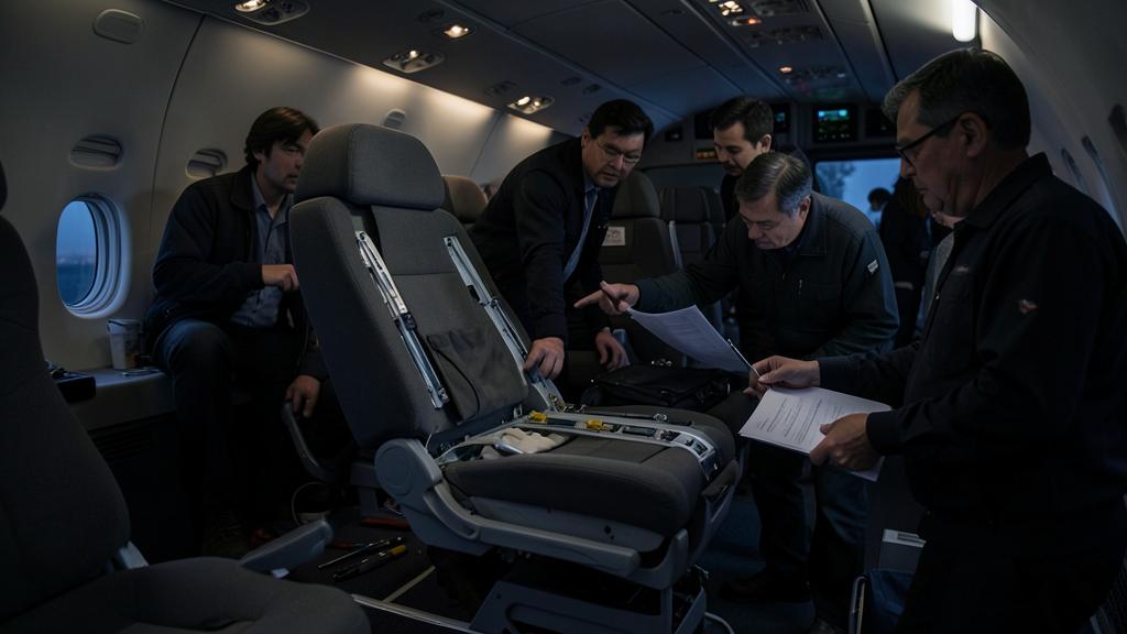
In practice, a departure rarely comes alone. Changing the seat while keeping the pitch also means changing the thickness of the seat back, hence the actual clearance, hence the contact analysis; it sometimes means changing the leg spacing, hence the holes used, hence the floor bay loaded. The classification of the modification, minor or major, and the approval route follow from that — but the engineering logic always comes before the administrative classification, never the other way round.
One family of cases deserves to be set apart: seats that do not face forward. A side-facing seat, an aft-facing seat, a crew rest seat or a divan in a business jet lounge are not covered by reasoning built on the longitudinal run alone. The load paths change direction, the restraint no longer works in the same way, and one falls back on complementary criteria — protection of the pelvis and the spine, shoulder restraint, lateral contact surfaces — that are established case by case with the authority rather than read off in a box. On a business jet interior, it is often that family which consumes most of the certification schedule, well before the conventional rows.
| Departure from the test article | What has to be demonstrated | Usual nature of the substantiation |
|---|---|---|
| Same seat, same pitch, same track type, equivalent floor zone | that the test report does cover the configuration as installed | similarity note and check of the fitting loads against the capacity of the track |
| Reduced row pitch, seat unchanged | that the head and the legs do not meet a closer or harder surface | trajectory analysis, then a head strike test if the analysis is inconclusive |
| Row placed in front of a bulkhead, a wardrobe or a galley | that no rigid surface enters the strike envelope | qualified padding, justified distance, or a test run with the actual monument |
| Modified seat: heavier screen, different cushion, three-point restraint | that mass, inertia and restraint geometry remain enveloped by the original test | delta test on the difference alone, or a complete new test depending on its scale |
| Same seat on another aircraft type or another floor zone | that the track and the floor beam react the leg loads in every direction | comparison with the aircraft manufacturer’s load map, local reinforcements if necessary |
What to open before pricing the job
Before committing to a retrofit, a handful of documents decide the fate of the project, and they are not all held by the same party. On the seat side: the complete dynamic test report, its conditions and limitations section, the list of attached masses taken into account, the exact definition of the fittings and the range of pitch covered. On the aircraft side: the map of allowable track loads, the degraded zones, the wear limits given in the maintenance data, and the condition survey carried out on the actual aircraft — an item regularly underestimated at the quotation stage, and a recurring subject of shop-floor discussion on the FL330 forum. On the operator side: the approved cabin layout, the list of authorised configurations, weight and balance, and the documentation describing what the crew must check before flight.
There remains a grey area, which is better acknowledged. No test covers every combination of seat, pitch, monument and floor zone; the demonstration proceeds by envelope and by similarity, and the boundary of the envelope is a documented engineering judgement, not something self-evident on a data sheet. That is where the value of a compliance file lies: in the traceability of the reasoning that connects the test article to the aircraft standing on the ramp.
For anyone preparing a certifying staff qualification or a cabin interior compliance review, the shift is worth anticipating: the questions are no longer about the 16 g figure, which everyone can recite, but about what the test had under its feet, about what was attached to the seat back in front, and about the way those two things were transposed to the real cabin.
The applicable certification specifications, the approved data of the aircraft manufacturer and of the seat manufacturer, and the operator’s approved documentation take precedence over this article, which is technical explanation only.
Questions fréquentes
Can a seat marked “16 g” be installed on any transport aeroplane?
No. The qualification covers an assembly comprising the seat, its fittings and a representative length of seat track, in a specific configuration of pitch and equipment. Installation additionally requires that the receiving track, floor beam and floor zone react the loads measured at the fittings, and that the environment of the row remains covered. These are two distinct approvals: that of the article, then that of the installation.
Does reducing row pitch force a new dynamic test?
Not systematically, but the question has to be addressed. A reduction in pitch brings the head closer to the surface in front and may bring a hard point into the strike envelope, which calls for a trajectory analysis and, if that is inconclusive, a head strike test. Pitch also carries requirements on access to the exits and on passageway width that are checked separately.
Why does the test impose a deformed floor before the pulse?
Because in a real impact the floor structure twists before the seat has finished being loaded. The rig sets one track out of parallel by ten degrees in the vertical plane and rolls one of the two by ten degrees, before the impact and during it. The seat must therefore prove that its fittings accommodate the misalignment without tearing out, which presupposes an organised flexibility of the leg structure.
Is a neighbouring monument substantiated in the same way as a seat?
No. A galley, a wardrobe or a stowage is substantiated against static inertia factors, whereas the passenger seat is substantiated against two dynamic pulses. Yet both demonstrations end up at the same track, which has to take the sum of the reactions. That is why the capacity balance for a length of track must be established globally, and not equipment by equipment.
What should be checked on the tracks of a second-hand aircraft before pricing a retrofit?
The geometric and metallurgical condition of the tracks over their whole length: ovalisation of the holes, wear of the flanges, corrosion under plates, condition of the splices, plugs and wear plates already fitted. What is already attached to the same length of track and the cable runs in the trough must also be surveyed. The allowable limits are given in the aircraft manufacturer’s maintenance data.
Is the manufacturer’s test report enough to approve the installation?
It is the starting point, never the conclusion. The installation file must show that the configuration as fitted remains within the envelope of the conditions and limitations of the report, or substantiate each departure by an analysis, a delta test or a complete test. To that are added the check of floor loads, the contact analysis and the update of the approved cabin layout.


Leave a Reply
You must be logged in to post a comment.