
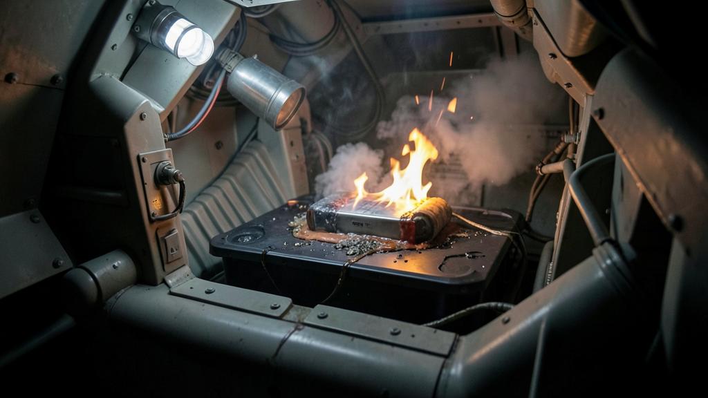
A battery certification programme is not trying to prove that no cell will ever fail. Nobody believes that, and no test campaign is built on it. What it has to prove is that the failure of one cell stays the failure of one cell. That sentence, harmless as it looks, reaches a long way past the pack: it decides how the cells are spaced, where the hot gas is allowed to go, and how long the structure above the pack has to hold its shape.
The starting assumption is that a cell will fail
Lithium-ion cells fail from causes that are not all under the designer’s control. A metallic particle left in the electrode stack during manufacture can eventually work its way through the separator. Charging at low temperature can plate lithium metal on the anode, and plated lithium grows dendrites. Mechanical damage can crush the stack locally. A failure in the balancing or protection electronics can overcharge a cell past the point where the cathode stays stable. Ageing narrows the margin on all of these at once.
Individually these events are rare. Multiplied by the number of cells in a propulsion-class pack, then by the fleet, then by the years the fleet will fly, they stop being rare. That arithmetic is why the requirement is not a reliability target for cells but a consequence requirement: whatever the cell does, the aeroplane keeps flying. Everything below follows from refusing to bet on the cell.
What one cell actually releases
Thermal runaway is a chain of exothermic reactions that outruns the cell’s ability to shed heat. It usually begins with the decomposition of the passivating layer on the anode, continues through separator softening and melt, and accelerates once the separator no longer keeps the electrodes apart. At the top of the chain the cathode itself decomposes, and depending on the chemistry it can release oxygen — which is the reason a runaway cell does not need the surrounding air to keep burning, and the reason smothering it is largely ineffective.
Three things leave the cell, and each attacks the neighbours differently.
Heat. The total energy released is larger than the electrical energy the cell was storing, because the cell is consuming its own materials as fuel. That surplus is chemistry-dependent rather than universal: an iron-phosphate cell and a high-nickel cell of the same capacity do not present the same event.
Gas. The vent stream is a mixture of hydrogen, carbon monoxide, carbon dioxide, light hydrocarbons and vaporised electrolyte, together with fluorinated species produced by the decomposition of the salt and the binder. It is flammable, it is toxic, and its volume is large compared with the free volume inside a densely packed enclosure. The pressure rise is not a side effect; it is one of the loads the enclosure has to be sized for.
Ejecta. Hot particles, molten material and, if the cell ruptures rather than vents as intended, fragments of the casing. This is the part that behaves least like a fire and most like a short directional jet.
The trap. Treating the event as a fire and reaching for fire-protection thinking alone. A runaway is a pressure pulse and a jet of hot gas in the first seconds, then a fire, then a long smouldering phase during which the pack can re-ignite after it appears to be out. A design that answers only the middle phase leaves the first and the last unaddressed.
When a lithium-ion battery cell fails, it releases heat, gas, and molten material. The heat can spread to other cells, the gas can create pressure and toxicity, and the molten material can damage nearby components. The goal is to stop this from happening so that only one cell fails, not the whole pack.
On a Boeing 787 in January 2013, a main battery with eight lithium-ion cells experienced a thermal runaway that spread from cell to cell. The redesigned installation added spacing and insulation between cells to prevent propagation, a steel enclosure able to contain a fire, and a vent line that directs the gases outside the aircraft, so that a cell failure no longer threatens the structure around it.
Three roads from one cell to the next
Propagation is not a single phenomenon. It has distinct paths acting on different timescales, and each is closed by a different measure. Naming them separately turns a vague requirement into tractable engineering problems.
| Path | Mechanism | Design answer | What it costs |
|---|---|---|---|
| Conduction | Heat travels through casings, busbars and cell holders into adjacent cells | Thermal breaks in the busbar, low-conductivity holders, spacing, a heat sink that pulls energy out of the path | Volume, mass, and electrical resistance where you wanted none |
| Radiation and hot gas | The free volume above and around the cells fills with hot gas that heats every surface it touches | Barriers between modules, controlled gas routing, reduced free volume or deliberate purge | Packaging complexity and a ducting path that must survive the event |
| Jet and ejecta impingement | The vent stream is directional and can play directly onto a neighbour’s casing | Vent orientation away from cells, a plenum that receives the jet, deflectors of a material that does not melt | Cell orientation constraints that fight energy density |
| Electrical | Cells in parallel with the failing cell discharge into its internal short, adding energy the failing cell did not have | Fusible links per cell or per group, topology that limits the parallel count seen by a single fault | Added resistance, added parts, added failure modes of its own |
Compartmentalisation is a heat-flow budget, not a wall
The instinct on first reading a non-propagation requirement is to put a barrier between the cells — useful, and incomplete. A barrier does not stop heat; it slows it. What the design has to guarantee is that the neighbouring cell stays below its own runaway onset temperature for as long as the event lasts — and the event lasts far longer than the visible flame.
That gives three levers, and every real pack uses a mixture of all three. Slow the heat, with insulating barriers, low-conductivity structure and ceramic or intumescent materials that keep their form when hot. Remove the heat, with cold plates, phase-change material or a coolant loop that takes energy out of the module during the event — which means the coolant loop itself becomes safety equipment and inherits the reliability requirement. Or move the neighbour, with spacing, which is the most effective measure and the most expensive one in a discipline where energy per unit volume is the whole point.
This is where the pack designer and the airframe designer stop being able to work separately. Spacing costs bay volume, insulation costs mass, and a cold plate costs a fluid loop that has to be routed, protected and inspected. The trade is made at aircraft level, which is why a battery installation drives structural layout rather than following it.
Venting: getting the gas out without building a pressure vessel
Once the gas is produced it has to go somewhere, and the choice between containing it and releasing it drives the whole enclosure design.
Containing it means the enclosure is a pressure vessel, sized for a deflagration inside a volume filled with a flammable mixture. That sizing is heavy, and the failure mode if you get it wrong is a case rupture that puts fragments into the airframe rather than gas into a duct. Releasing it means a relief path — burst discs or pressure panels opening into a plenum, and from the plenum overboard. That is the route the large transport installations certified since have generally taken, and the redesign of the 787 battery installation after the 2013 events is the reference case: a stronger enclosure, cell spacing, and a vent line taking the effluent outside the fuselage rather than into the equipment bay.
An overboard vent then creates its own questions, each a certification item in its own right. Where the outlet sits relative to engine, APU and air conditioning inlets. Whether the duct survives the temperature and the pressure pulse. Whether the outlet stays clear in icing conditions, and whether a frangible cover opens reliably at altitude. Whether the effluent flows back over a control surface, a sensor or a static port. None of these belongs to the pack supplier alone.
The right reflex. Read the vent path as a system — source, route, outlet, consumers downstream — exactly as you would read a bleed air or a fuel vent system. Treating it as an accessory of the battery is how the interfaces get missed.
What the surrounding structure has to survive
Structure does not have to melt to stop being structure. It only has to lose enough strength or stiffness for long enough, and the temperatures at which that happens are far below what a runaway produces locally.

| Material | Behaviour with temperature | Consequence for the installation |
|---|---|---|
| Aluminium alloys | Yield and ultimate strength fall substantially long before melting, and the loss is largely permanent after a sustained exposure | A frame that looks intact after the event may no longer carry its design load; post-event inspection criteria must be defined, not improvised |
| Carbon fibre with an epoxy matrix | The matrix passes its glass transition at a modest temperature; compression and shear capability go first, tension last | A composite floor or keel above a pack loses exactly the properties that were carrying the installation loads |
| Titanium and steel | Retain useful properties much higher, at a mass and cost penalty | Often the answer for local shields, deflectors and vent ducting rather than for whole structures |
| Sealants, wiring insulation, elastomers | Degrade at temperatures well below any structural threshold | Electrical separation and fluid tightness are lost before strength is, which is why routing matters as much as material choice |
Two installation architectures produce two different problems. In a bolted-in pack, the enclosure is equipment and the airframe around it is structure, so the question is how much heat crosses the interface and for how long. In an integrated pack, where the case is part of the primary load path, the enclosure is both the container of the event and the thing the event is attacking. The second architecture buys mass and volume, and it buys them by making the containment argument considerably harder to close.
The same logic extends to whatever shares the bay: flight control routing, hydraulic lines, essential harnesses and, in a hybrid installation, fuel lines and tank boundaries. The question is never only whether the pack contains its own event, but what else sits inside the volume that event can reach.
Fireproof and fire resistant are durations, not adjectives
Aviation has two long-standing terms of art here, and neither is a loose adjective. The airworthiness codes define them by comparison: a fireproof part withstands the heat of a fire at least as well as steel in dimensions appropriate for the purpose, a fire resistant one at least as well as aluminium alloy. The test standards turn that comparison into a duration against a burner whose temperature and heat flux the standard fixes rather than the designer, conventionally five minutes for fire resistant and fifteen for fireproof. Declaring a part fireproof is a claim about a test result, not a description of an intention.
Be clear about what that test represents. The standard flame is a steady, well-characterised source; a cell runaway is a short directional jet, then a fire, then a long low-intensity phase. A part qualified against the standard flame has passed a meaningful floor, but the qualification is not a simulation of the event, and the argument that it covers the event has to be made explicitly. That is why battery installations tend to be certified through dedicated testing rather than by pointing at existing fire-protection qualifications.
Proving it: triggering a cell on purpose
Every propagation test has the same shape. You make one cell fail deliberately, and you instrument everything around it to show that the second cell did not follow. The difficulty is that there is no neutral way to make a cell fail: each trigger method distorts the event it is supposed to represent, and the choice of method is an argument the applicant has to defend.
| Method | What it represents well | What it distorts |
|---|---|---|
| Film or cartridge heater | A repeatable, controllable onset; good for comparing two designs | Adds external energy the real failure would not supply, and warms the neighbourhood before the event starts |
| Nail or blade penetration | A local internal short, close to the particle-defect mechanism | Creates a conductive path out of the cell through the nail, and fixes the short at one geometric point |
| Overcharge | A realistic protection-failure scenario end to end | Changes the cell’s chemistry and gas content before runaway begins, so the effluent is not that of a defect-driven event |
| Implanted internal short device | Closest to a genuine internal short with no external heat or path | Requires modifying the cell in manufacture, so the test cell is not the production cell |
Choosing the trigger is only half of it. The other half is the conditions, and a credible campaign picks the worst of each: the cell position that gives the neighbours the least escape route, which is usually not the corner; the state of charge that maximises released energy; the ambient temperature at the top of the envelope; and the pressure altitude, which changes how the gas disperses and where the mixture sits relative to its flammability limits. A result obtained at sea level does not transfer upward without an argument.
Why the applicable requirement keeps moving
There is no single settled paragraph that certifies a propulsion battery. Large-aeroplane airworthiness codes were written before packs of this energy existed, so the requirements arrive as special conditions issued for the specific project, drawing on a recognised test standard for rechargeable lithium batteries and on the fire-protection and equipment provisions already in the code. For electric and hybrid propulsion, and for the VTOL category, dedicated special conditions and their means of compliance carry the load. The practical consequence for a project team is that the applicable requirement is negotiated and documented early, and that it will not look identical to the last programme’s.
Aviation and the automotive world also part company here. Road-vehicle standards have generally been framed around giving occupants time to get out: a warning, then a defined interval before the passenger compartment is affected. An aeroplane in cruise cannot pull over and walk away, which is why the aviation requirement is expressed as containment rather than as escape time. Borrowing an automotive test result without addressing that difference loses certification reviews.
The idea worth keeping
Non-propagation reads as a chemistry requirement and behaves as a structural one. Once you accept that a cell will fail, what follows is about heat flow, gas routing and how long the metal and laminate around the pack keep doing their job — which makes a battery installation an airframe problem that happens to contain cells. Design discussions of this kind, and the certification experience behind them, come up regularly on the FL330 professional forums.


Leave a Reply
You must be logged in to post a comment.