
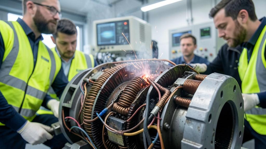
A turbine engine is certified around a failure that ends with the engine stopped, and around an aeroplane that keeps flying without it. An electric propulsion unit fails differently: it loses a coil, an inverter leg, a control channel — and it keeps turning. The safety argument therefore cannot be a reserve of power. It has to be a demonstration that the machine degrades in known, bounded steps, and that those steps are genuinely independent of one another.
Two propulsion systems, two safety arguments
Engine certification and aeroplane certification have been sharing the work for decades, and the split is clean. The engine code asks the manufacturer to show that the engine delivers a declared rating and that when it fails it does so without producing a hazardous effect: no uncontained rotor burst, no uncontrolled fire, no inability to shut it down. The aeroplane code then assumes, on a multi-engine aeroplane, that an engine can be lost outright, and asks for climb gradients, obstacle clearance and controllability with the remaining ones. The margin lives at aeroplane level, in the form of a second engine and of performance figures computed as if the first had stopped.
That division works because the dominant failure of a gas turbine is close to binary in its effects. Blade damage, a surge that will not clear, an oil fire, a fuel control fault — whatever the mechanism, the crew action converges: shut it down and fly on what is left. Power margin is a meaningful currency precisely because the failure removes all of it at once.
An electric propulsion unit is not one thing that stops. It is a set of electromagnetic circuits, each with its own semiconductors, drivers, current sensors and control logic, all sharing one rotor and one shaft. Most of the credible faults are partial: one phase open, one power module shorted, one temperature sensor lying, one control channel commanding a torque nobody asked for. Adding twenty per cent of installed power answers none of them.
Turbines fail all at once, so safety relies on having a backup engine. Electric motors fail in pieces, so safety relies on proving each part can fail without taking the whole system down.
A six-phase electric motor on an eVTOL aircraft loses one phase due to a shorted coil. The remaining five phases continue providing torque, but the motor must prove it can handle this degraded state without overheating or creating dangerous vibrations during a critical hover phase.
A permanent magnet cannot be switched off
The single fact that reshapes the whole demonstration is that excitation in a permanent-magnet machine is not a supply the designer controls. As long as the rotor turns, the magnets induce a voltage in every winding facing them. Open the contactor, cut the drive, pull the circuit breaker: the voltage is still there, and if the winding is shorted, so is the current.
A turn-to-turn short is therefore self-sustaining. The shorted turns see the induced voltage across a very low impedance, the resulting current dissipates heat exactly where the insulation has already failed, and the loop closes on itself. The same current produces braking torque, which on a wing-mounted unit becomes drag on one side, and on a distributed-propulsion aircraft becomes a yawing moment that has to be trimmed or countered. A turbine on fire can be starved of fuel. A shorted permanent-magnet winding can only be starved of rotation.
The answers to this are structural rather than procedural, and they are what a certification review looks at. Machines can be proportioned so that the steady-state short-circuit current settles near the rated current rather than several times it — a choice of winding inductance, made at the drawing board, not a protective device added afterwards. Coils can be wound one per tooth so no two phases share a slot, keeping a failed coil away from its neighbours. A decoupler can remove the rotor from the shaft. A wound-field or reluctance machine gives back the ability to remove excitation, at a cost in mass and efficiency.
The trap. Counting phases and calling them redundancy. A six-phase machine driven by two three-phase inverters has two failure domains, not six; if those inverters share a gate-drive supply, a coolant loop and a controller, it has one. What belongs in the safety analysis is the count of independent failure domains, and it is smaller than the datasheet figure.
What actually counts as a lane
The useful unit of analysis is not the phase but the lane: a winding set, its inverter, its gate drivers, its DC feed and protection, its current and position sensing, its control channel and its share of the cooling. A lane is credible only if a fault anywhere inside it stops at its boundary — electrically, magnetically, thermally and physically.
Each of those four words carries a requirement. Electrical separation means separate DC feeds and separate means of isolation, not two inverters hanging off one bus through one contactor. Magnetic separation means the fault current in one winding set does not couple into another, which drives the slot and tooth arrangement. Thermal separation means a coil running away does not cook its neighbour before the fault is detected. Physical separation means terminations and harness routing that a single chafe or a single fluid leak cannot take out together.
| Question | Gas turbine | Electric propulsion unit |
|---|---|---|
| Dominant failure signature | Close to all-or-nothing at unit level | Partial and graded: a lane, a leg, a channel |
| How the failure is stopped | Fuel is cut; the unit stops | Excitation may be uncontrollable while the rotor turns |
| Where the margin lives | At aeroplane level: one engine inoperative performance | Inside the machine: torque still available after a lane is lost |
| Limiting physical quantity | Gas and metal temperature, hence a time-limited rating | Current and winding temperature, hence a thermal budget |
| Nature of the demonstration | Mature code, long service history, established test schedule | Fault injection on a running machine; little service history |
| What the crew can do | Identify, shut down, secure | Often nothing beyond accepting the degraded state |
Power margin is the wrong currency, thermal budget is the right one
A turbine has very little short-term overload capability: it is limited by temperatures that appear within seconds, which is why takeoff ratings are time-limited and why exceeding them is an engineering event. An electric machine is the opposite. Current is limited by magnetic saturation and by semiconductors, both of which tolerate large transients; what does not tolerate them is the accumulated heat in the copper, in the insulation and in the magnets. A machine can produce far more than its continuous torque briefly, and nothing like it for an hour.
This makes a headline power figure almost meaningless on its own. A rating for an electric propulsion unit is a triplet: torque, duration, and the thermal state you started from. The same unit is honest at two very different numbers depending on whether the coolant is cold or at the end of a long climb on a hot day.
And here is why oversizing does not buy safety. Losing a lane means the surviving lanes carry more current to produce the same torque. Losses in a winding rise with the square of current, so the thermal budget you were relying on shrinks at exactly the moment you need it. The apparent reserve was conditional on a temperature the fault has just destroyed. A reserve of power that evaporates in the failure case is not a safety argument; it is an accounting entry.
Electric motors can handle short bursts of extra power, but their real limit is heat. If a part fails, the remaining parts get hotter, and that extra power disappears fast.
A 200 kW electric motor on a regional aircraft is rated for 30 minutes at 250 kW during takeoff. After losing one of three lanes, the remaining two must handle 250 kW, but their thermal limit drops from 30 minutes to 10 minutes due to increased heat.
The rating that matters is the degraded one
The figure a certification discussion should converge on is the internal equivalent of one engine inoperative: the torque still available after the worst credible single failure, for the duration of the flight phase that needs it, at the hottest day and the highest altitude in the declared envelope, starting from the thermal state that phase realistically begins with.
Several other quantities travel with it. Torque ripple and vibration change when a lane drops out, which is a structural and gearbox question as much as an electrical one. Current in the surviving lanes rises, propagating the failure into the harness, the contactors and the energy source. And reconfiguration — detect, isolate, redistribute — is far too fast for a crew procedure, so it lives in a control law developed to an assurance level consistent with the hazard.
| Failure | Immediate effect | What lane redundancy buys | What it does not solve |
|---|---|---|---|
| Turn-to-turn short | Sustained circulating current, local heating, braking torque | Confines the fault to one winding set if separation is real | The drag and the heat, which persist while the rotor turns |
| Inverter leg or module short | Loss of that lane, possible short across the winding set | Torque continues on the remaining lanes | The DC bus disturbance and the current step upstream |
| Gate driver or control channel fault | Loss of control, or torque that was never commanded | Isolation of the affected channel | Erroneous torque, which is a hazard of its own |
| Position sensor fault | Wrong commutation, torque collapse or oscillation | Nothing, unless sensing is duplicated per lane | Undetected drift, which duplication alone will not catch |
| Loss of coolant flow | Rapid thermal rise across the whole machine | Nothing, if the cooling loop is shared | The derating that follows, and its effect on the phase in progress |
| Bearing, shaft or gearbox failure | Mechanical loss of the unit | Nothing at all | Everything: this part is argued structurally, not by redundancy |
Where lane independence quietly disappears
Redundancy on a block diagram is cheap. What a common cause analysis looks for is everything the lanes share, whether the designer meant them to or not. Some of it is irreducible: one rotor, one shaft, one set of bearings, one propeller or fan. That part of the machine has no redundancy and must be defended with structural substantiation, inspection intervals and margins — the same way a rotating turbine disc has always been defended.
| Shared item | The question that gets asked |
|---|---|
| Coolant loop, pump, heat exchanger | Does a single loss of flow take every lane at once, and what is the declared power after it? |
| DC bus, contactors, protection | Can one fault propagate upstream and reach the other lanes through the bus? |
| Energy storage and its management | Is a lane still a lane when both draw from the same pack and the same controller? |
| Control software and calibration data | Would the same erroneous parameter or the same latent fault appear in every channel simultaneously? |
| Harness routing and connectors | Does one chafe, one fluid leak or one fire zone reach more than one lane? |
| Environment: vibration, altitude, humidity | Do reduced pressure and moisture degrade insulation in all lanes at the same rate? |
That last line deserves more attention than it gets. Insulation behaviour depends on pressure, and the machine spends its life climbing away from the conditions its materials were qualified in. Partial discharge absent on a sea-level bench can appear at cruise altitude, and it is a wear mechanism: it does not fail the machine the day it starts. Every lane breathes the same air, so this is a common cause by construction.
Why the demonstration ends in a test cell
Analysis sets up the argument; it does not close it, because the faults that matter are the hardest to model. A turn-to-turn short has an unknown contact resistance, it may arc, it evolves as it heats, and its thermal coupling to the next coil depends on impregnation quality that varies from unit to unit. Simulation does not settle what that fault does to its neighbour.
So the faults are injected. A turn is shorted on a machine running at speed and load; a phase is shorted; an inverter leg is opened; a gate driver is killed; the coolant is cut; the position signal is frozen or offset. What is measured is what the analysis claimed: the actual fault current, the actual braking torque, the temperature reached at the boundary of the lane, whether the fault stayed inside it, and the state of the insulation afterwards. Then the machine is stripped and looked at.
The right habit. Draw the failure domain map before the power sizing. Establish which lanes exist, what each shares, and what the machine still delivers after the worst single failure — then size for that number, not the brochure figure. Doing it in the other order buys the redundancy twice.
A certification basis still being written
There is no settled engine code for this. Electric and hybrid propulsion is handled through special conditions and means of compliance published as projects arrive, not through a mature body of rules built on service experience. That has two consequences.
The first is that the architecture has to be defensible before the rule text exists. What is negotiated is the means of compliance, so the asset is an honest failure-domain story — one that survives a common cause analysis run by someone who did not design the machine. The second is that the pieces around the machine come with established frameworks of their own: development assurance for the controller software and its complex hardware, environmental qualification for the installation, and a separate problem for the energy source. EASA and the FAA have not converged on every point, so a claim that something is accepted only means something once you say by whom.
What follows on the industrial side
An argument built on lane independence has to be reproduced on every unit that leaves the factory, which turns a design property into a production control problem. Impregnation quality, insulation process, magnet batch, termination torque, the routing of two harnesses that must never share a chafe point: each is a place where a lane stops being independent without anything looking wrong.
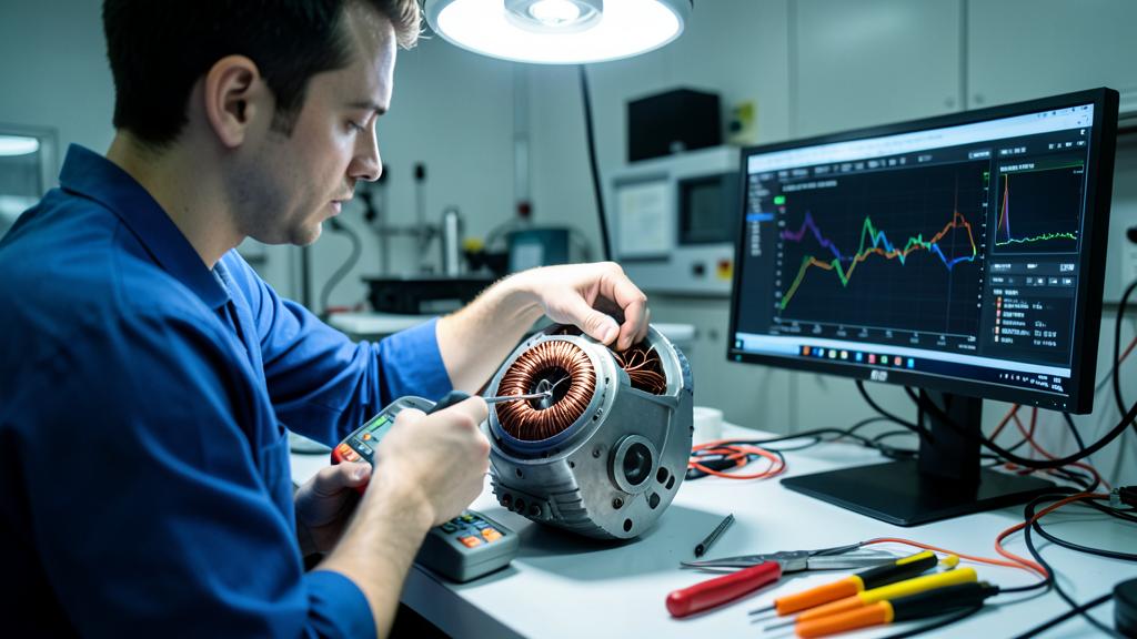
Maintenance inherits the same logic. There is no borescope equivalent for a stator, so monitoring moves to what can be measured electrically — insulation resistance, partial discharge, current signature, temperature history — and the programme has to state what happens when one lane is degraded but the machine still delivers its declared power. Whether a lane is replaceable at all, and at what level of organisation, is an architecture decision disguised as a support decision, and one usually argued out on forums.fl330.com long before it reaches a certification plan.
None of this makes electric propulsion harder to certify than a turbine. It makes it different, and the difference sits in one place: the failure that matters does not stop the machine, so the answer cannot be a spare. It has to be a boundary, proven where it can be broken.


Leave a Reply
You must be logged in to post a comment.