

The retrofit case promises a few percent less fuel burn, the modification goes onto half the fleet, and six months later the fuel-consumption tracking shows almost nothing on the short-haul network — while the same airframes, flown one summer on longer rotations, post clear differences. Nothing abnormal about that: a wingtip device only reduces one component of drag, the one that matters when the aircraft is heavy, high and slow. The rest of the time it does nothing but carry its own mass, wetted area and lever arm. The only number that counts is the one your own operation produces.
What a wingtip actually produces
Lift exists because a pressure difference is established between the lower and upper surfaces. At the tip, nothing sustains that difference any longer: the air spills around the end, a vortex sheet detaches from the trailing edge and rolls up into a wingtip vortex. This wake induces a downward velocity component on the wing itself; the local relative wind is tilted downward, and the lift vector, always perpendicular to that local relative wind, tilts with it. Its projection onto the flight axis yields a resisting force: induced drag. It does not come from friction but from the energy cost of the vertical momentum imparted to the air to support the aircraft.
The useful consequence is that this drag depends on the square of the lift coefficient and varies inversely with aspect ratio, corrected by a span efficiency factor that reflects how far the lift distribution departs from the optimal distribution. In level flight, the required lift coefficient varies as the inverse square of speed: induced drag therefore decreases as speed rises, while friction and form drag increase. The sum traces the familiar dish-shaped curve, whose minimum defines the maximum lift-to-drag speed. The whole question of the wingtip device lies there: on which side of that dip does the aircraft spend most of its time?
Wingtip devices reduce drag when the plane is heavy and flying slowly, like during takeoff or high-altitude cruise. But when flying fast and light, the extra weight and drag from the device can cancel out the benefits. The actual savings depend on how you fly the plane most of the time.
On an Airbus A320 with blended winglets, the device reduces drag by about 3.5% at cruise altitude (35,000 feet, Mach 0.78, MTOW). But on a 300nm short-haul flight at lower altitude, the fuel savings might be only 1-2% due to the extra weight and drag of the winglets.
Three situations place the aircraft on the side where induced drag weighs heavily: the climb, where required lift is high and speed moderate; high-altitude cruise early in the flight, where the low air density demands a high lift coefficient; and the end of the approach. Conversely, low-altitude cruise at high speed, with a lighter aircraft, sits on the side where friction and form dominate. That is already half the answer to the operational balance.
What the device actually does
Two images circulate, and both are wrong. The device does not recover the energy of an already-formed vortex, and it does not plug an air leak. What it does is more subtle: it alters the spanwise circulation distribution and the geometry of the shedding vortex sheet. Placed in a local flow that is already deflected — outward under the wing, inward above it — a roughly vertical lifting surface develops a lateral force whose resultant has a component directed forward. That component is thrust, in the literal sense, and it offsets part of the induced drag.
The engineer’s language prefers the other formulation: the device increases the effective span, and hence the effective aspect ratio, without necessarily lengthening the geometric span. The merit criterion is therefore neither the added area nor the height of the device, but the ratio between the effective-span gain obtained and the added root bending moment accepted in exchange. The whole design follows from this trade-off, including the curvature of the blend, the twist and the camber law of the device itself.
Because a poorly blended device costs more than it earns. The junction creates interference between two lifting surfaces that see one another; if the curvature is too abrupt or the incidence poorly chosen, local separation or overspeed sets in, form drag rises and eats into the benefit. The same mechanism explains why the gain degrades near the drag-divergence Mach number: where the local flow is already close to sonic, the junction becomes a serious candidate for the onset of a shock.
Three families, three trade-offs
Industrial solutions differ less in appearance than in how they distribute the trade-off between aerodynamic gain, geometric span and bending load. A low-height fence barely touches the structure but makes no claim to a significant cruise gain. A blended winglet seeks the best gain-to-bending ratio by rising rather than extending. A raked wingtip extension genuinely lengthens the wing and pays more in high cruise, at the cost of the longest lever arm and a geometric span that can push the aircraft into a different aerodrome category. A split-tip device, by distributing the surface above and below the wing plane, gains effective span without adding height above the wing.
| Family | Aerodynamic principle | Geometric span | Root bending | Regime where it pays off |
|---|---|---|---|---|
| Tip fence | Short barrier disrupting the roll-up of the vortex sheet | Unchanged or nearly so | Marginal increase | Modest gain, spread across the whole flight envelope |
| Blended winglet | Lifting surface with a progressive blend, effective span increased through height | Slight increase | Moderate increase | Climb and high-lift cruise |
| Raked wingtip extension | Real lengthening of the wing, load redistributed outboard | Clear increase | Highest increase | Long, high cruise, heavy aircraft |
| Split-tip device | Surface distributed on either side of the wing plane | Slight increase | Moderate increase, better distributed | Cruise, constrained by ground clearance and hangar height |
This table also explains why the airport constraint weighs as heavily as aerodynamics in the choice. The aerodrome reference code letter is read from the ICAO table on two entries, wingspan and main gear track, and the step from letter C to letter D occurs at thirty-six metres of span. Crossing that threshold means a different required taxiway width, a different stand clearance, and sometimes compatibility with an entire network’s jet bridges. A cruise gain that rules out half the stations is not a gain, and the comparison must be made station by station, not on the home-base figure alone.
The flight regime decides the balance
The percentage shown in a sales case is almost always a drag reduction measured at a reference cruise point: a given weight, altitude and Mach number. It is not wrong, it is a single data point. Block fuel, by contrast, integrates taxi, climb, cruise and descent, and it carries the added mass through every one of those phases, on every sector, including the ones where the device contributes nothing.
| Regime | What dominates drag | Effect of the device | Net balance |
|---|---|---|---|
| Takeoff and second segment | Induced drag, high lift at moderate speed | Improved climb gradient | Can buy takeoff weight on runways limited by obstacles or by temperature |
| Initial and intermediate climb | Induced drag | Significant reduction | Favourable, all the more so when the aircraft is heavy |
| High cruise, heavy aircraft | Induced drag still significant | Significant reduction | The most favourable regime |
| Low cruise, lightened aircraft, high speed | Friction, form, compressibility | Added wetted area | Neutral to unfavourable |
| Very short sector, weight-limited at takeoff | Little cruise, many transient phases | Mass of the device and its reinforcements | The penalty is taken out of the payload |
The trap. In a mixed fleet, two aircraft of the same type no longer share the same data. The modified sub-fleet has its own takeoff and landing tables, its own wingtip clearance while taxiing, and sometimes its own limiting weights. Applying one aircraft’s data to the other out of habit is a silent error: nothing lights up, and the gap only shows itself the day the runway is short, wet, or the taxiway narrow.
The right reflex. Treat the sub-fleet designator as a limitation: check it on the operational flight plan and in the performance module before entering the first piece of data, and require that the ground clearance chart displayed at the stand match the day’s registration. The same reflex applies when preparing a positioning flight after a device replacement.
What the structure absorbs
Adding a lifting surface at the tip means adding a load at the end of the airframe’s longest lever arm. But most of the added root bending moment does not come from the device’s own weight: it comes from the outward shift of the half-wing’s centre of pressure. The device reloads the tip, and it is this redistribution that the torque box must absorb, at limit load as at ultimate load, under manoeuvre factor as under gust.
The design has an elegant lever against this penalty: sweeping the device aft so that its centre of pressure sits behind the wing’s elastic axis. Under load, the resulting torsion twists the tip nose-down, which reduces local incidence and unloads the outer wing. Here, aeroelasticity works for the engineer: it clips the most severe load cases and allows the aerodynamic gain to be held with an affordable strengthening. This is not a side effect, it is a design parameter.
The rest of the bill is more mundane. A concentrated mass at the wingtip lowers the wing’s natural bending and torsion frequencies, so the flutter envelope must be re-examined, sometimes with adjustment of the mass distribution. The fatigue load spectrum changes, which translates into new inspection thresholds and intervals on the outer torque box, attachment fittings and skins. A vertical surface placed far out in span finally alters the lateral derivatives: effective dihedral, directional stability, Dutch-roll damping. Flying qualities therefore have to be re-demonstrated, which can lead to a revision of the demonstrated crosswind or an adjustment of the control laws. The weight given up at takeoff is never that of the device alone: it includes its reinforcements.
What the ground and maintenance absorb
A taller or wider wingtip shifts clearance envelopes that nobody was checking any more. Clearance from ramp equipment, height under hangar doors, turning radius at the end of the taxiway, the rendezvous point of a pushback tractor: all parameters to revalidate station by station. Ground equipment strikes, moreover, rank among the recurring causes of damage recorded on these parts, precisely because they occupy a volume that habit does not anticipate.
Lightning adds to the file. Wing extremities are initial-attachment zones, and the device becomes the extremity: it needs skin protection, electrical bonding continuity through to the structure, and a proper re-installation of the static dischargers, often relocated in the process. Navigation and anti-collision lights migrate at the same time, which creates new minimum equipment list items for an older type. The device’s structure is frequently composite, with narrower repair limits than the surrounding metal, sensitivity to low-energy impact whose visible trace is faint, and hence delamination checks to be carried out after any suspected impact, even without a surface mark.
The second trap. The device’s surfaces are among those to be treated and checked during ground de-icing, and they are poorly lit, high up, and remote from the usual observation point. Residual contamination at the wingtip acts exactly where the device is supposed to work: it degrades lift on the outer sections, advances separation toward the tip, and takes away the gain paid for at takeoff at the moment it is needed most.
The reflex that avoids it. Have the device explicitly named in the de-icing report, as a surface in its own right and not as part of the wing, and verify that the final contamination check includes a viewpoint that actually sees it. The same naming requirement applies in the maintenance programme for the inspection tasks arising from the modification.
Doing the sums on your own network
The useful method is not to argue over the manufacturer’s percentage, but to weigh it against four quantities every operator possesses: average sector length weighted by number of flights, the cruise level actually flown, the average takeoff weight, and the proportion of departures limited by a maximum weight rather than by offered payload. The first two decide induced drag’s share of total drag, and hence the size of the gain. The last two decide what the added mass costs: fuel if the aircraft is not weight-limited, payload if it is. On a network where a significant share of departures is weight-limited, the penalty changes nature and becomes a loss of revenue.
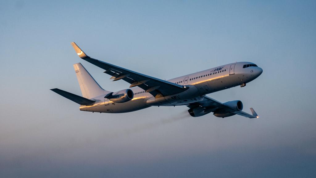
In your documentation, a few points deserve a named check. The flight manual supplement specific to the modification, which carries the sub-fleet’s performance data and, where applicable, revised limiting weights. The operational status of an airframe whose device has been removed or replaced with a non-conforming part after damage: is the hybrid configuration covered, with which data and which limitations? The maintenance programme, for the tasks added on the outer torque box and fittings. The minimum equipment list, for relocated lights and dischargers. And the ground clearance chart, which must be specific to the registration and not to the type.
One grey area remains, and it is a candid one: the performance credit is calculated on a device that is intact and clean. Nobody tabulates the aircraft with an eroded device leading edge, a composite repair in place, or a blend slightly deformed by an impact repaired within tolerances. The mechanism only says that the gain degrades; quantifying it belongs to the type certificate or supplemental type certificate holder. For anyone preparing a type rating or a recruitment interview, this is precisely where the difference lies between reciting a percentage and explaining a mechanism: knowing why the same device pays off handsomely in a heavy climb and nothing on a short sector flown low, and knowing where, in the operator’s documentation, the sub-fleet’s own data can be found.
The applicable certification specifications, the type’s flight manual and its supplements, and the operator’s approved documentation take precedence over this article, which sets out only physical mechanisms and design principles.
Questions fréquentes
Why does a wingtip device pay off less on short sectors?
Two effects compound. A short sector is flown at a lower level and a lower lift coefficient, a regime where induced drag is only a modest share of total drag, so the device has little to remove. And the mass of the device and its reinforcements is carried on every takeoff, whatever the distance. The block-fuel balance only turns positive beyond a threshold specific to the type and the design.
Does the device recover the energy of the wingtip vortex?
No, that image is misleading. The device alters the spanwise circulation distribution and the geometry of the vortex sheet, which amounts to increasing the wing’s effective span. Placed in an already-deflected local flow, it develops a lateral force with a forward-directed component. It is this component that offsets part of the induced drag.
Why prefer a vertical surface to a simple span extension?
A horizontal extension is more efficient per unit area, but it places the added load at the end of the longest lever arm and increases the root bending moment more, hence the required reinforcement and the mass. It also increases the geometric span, which can change the aerodrome code letter and close off stations. The vertical surface delivers less but costs less on both counts.
What changes for the crew on a mixed fleet?
The modified sub-fleet has its own takeoff and landing performance data, sometimes revised limiting weights, and always a different wingtip clearance while taxiing and parked. This data must be called up by sub-fleet designator, not by type. The ground clearance chart used at the gate must match the day’s registration.
Does a damaged or removed device still permit flight?
The answer is written in the type’s approved data or the supplemental type certificate: some provide for a ferry configuration with speed and weight limitations, others exclude it. The published performance credit assumes an intact, clean device, so no extrapolation can be improvised on the line. The question is settled in the flight manual supplement and with the continuing airworthiness management organisation, before departure, not after.
Why insist on de-icing the wingtip?
Residual contamination on the outer sections and on the device degrades lift exactly where the aircraft relies on it during the initial climb, and advances separation toward the tip. Yet these surfaces are high up, poorly lit, and remote from the usual observation point. Having them explicitly named in the de-icing report, rather than implicitly folded into the wing, avoids the blind spot.


Leave a Reply
You must be logged in to post a comment.