
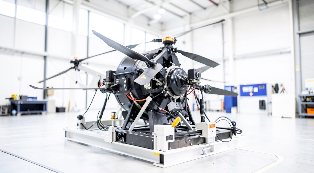
A tilt-rotor demonstrator, halfway between hover and cruise, loses an inverter on the left side. The flight control law knows what to do with the motors that remain; what it cannot say is where to go. Returning to hover demands power that is no longer certain, continuing demands a speed not yet reached, and between the two there is no fallback comparable to a glide or an autorotation. This question, posed at every point of a continuum, is the real lock on powered-lift programs.
Conversion is not a configuration, it is a continuum
On an airplane, configuration is a discrete and short notion: a few flap settings, gear up or down. Each combination is a state that gets demonstrated — stall speeds, performance, handling qualities, behaviour after a failure — and the list fits on one page. It is this finite character that makes certification practicable: the retained states are demonstrated, the others are prohibited.
A powered-lift aircraft has no such luck. Between hover and cruise, the state variable is continuous: nacelle angle for a tilting-rotor layout, relative rotor speed for a lift-plus-cruise layout, and in both cases a share of weight carried by the wing that progressively moves from nothing to everything. Every intermediate value is a configuration in the certification sense: it has its own low boundary, its own control authority, its own trim, and its own response to failures. They cannot be enumerated. And the wing, early in the conversion, sits in the rotor wash: its local angle of attack is not the one the flight path would suggest, so the share of weight it actually carries is already a quantity that is hard to measure.
Hence the construction every applicant adopts: a corridor. The conversion is bounded from below — below which, at that tilt angle, the wing-plus-rotors combination can no longer hold level flight — and from above, where it is the rotors that cap out: retreating-blade stall, flapping, hub moments, tilt-actuator loads. The corridor is wide at both ends and narrow in the middle. The whole case consists of demonstrating that the aircraft stays within it, and that crossing it has no catastrophic consequence.
Powered-lift aircraft don’t have fixed states like airplanes. They move smoothly from hover to cruise, and every tiny step in between counts as a new state. This makes testing and certifying them much harder because you can’t just test a few setups—you have to prove it works at every possible point in that transition.
Imagine a tilt-rotor aircraft like the Bell Boeing V-22 Osprey. During its transition from hover to forward flight, at 80 knots, the rotors are at 45 degrees. If a rotor fails here, the aircraft must keep flying without losing control. But unlike a plane, there’s no simple “stall speed” to test—every small change in speed or tilt angle creates a new test case.
The authority trough, and the absence of a characteristic speed
The authority of aerodynamic surfaces follows dynamic pressure, hence the square of speed: at low speed it is negligible, and it stays that way longer than one might imagine. Rotor authority is, conversely, maximal at hover, where differential thrust produces considerable moments, then decays as the rotors tilt, offload or stop. The two curves cross in the middle of the corridor, and at that crossing the better of the two means is at its lowest. The trough falls exactly where the aircraft is most disturbed: its own wake, wash over the wing and tail, ground effect if the manoeuvre is low, gusts whose relative effect grows as speed drops.
On an airplane, these boundaries have names and are measured according to established techniques: a stall speed is obtained at a specified rate of deceleration, marked by a defined event; a minimum control speed is demonstrated against an explicit heading and bank criterion. There is nothing of the kind here. The low boundary does not announce itself with a nose-down break but with a sink rate that can no longer be arrested and, most often, with control-allocation saturation — a software notion, not an aerodynamic one. What, then, is the event? The applicant proposes a criterion, the authority accepts it or not, and the test technique is negotiated before the flight instead of being read from a handbook. A test point can be discarded after the fact, not for what it showed, but for how it was obtained.
The trap. A conversion limit expressed in airspeed assumes that an airspeed is available. Yet below a certain value, the airspeed probe sits in the rotor wash: the reading is no longer a speed but a wake measurement, and it is in the lower part of the corridor that it degrades. The crew and the conversion scheduler need to know where they are at precisely the moment when the quantity that tells them is least reliable. Look for which source the limit is actually built on, and what is left of it when that source is lost.
A failure no longer has one severity, it has a severity per instant
The classic safety-assessment method identifies failure conditions, assigns them a severity, derives a probability objective from it, then verifies that the architecture meets it. It assumes one can point to the single most critical moment of the flight. In a conversion, that point does not exist: the severity of a failure is a function of position within the corridor. Losing a lift rotor near hover forces the allocation to recover both lift and moment elsewhere at the same time; the same loss in mid-conversion is sometimes handled by pushing forward. An asymmetric tilt is almost nothing at one end and design-driving in the middle. The matrix is no longer ‘failure times flight phase’ but ‘failure times position in the corridor times energy state’.
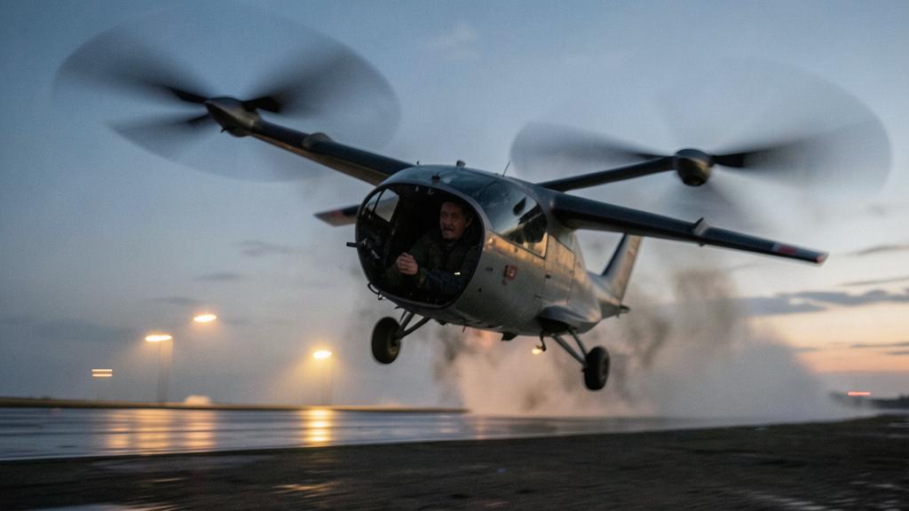
Above all, the fallback is missing. An airplane that loses propulsion glides, with a known glide ratio and a reach envelope the crew can estimate. A helicopter autorotates, and that capability is demonstrated, quantified, trained. An aircraft carried by its rotors has, in the common configurations, neither: the rotors are small, often fixed-pitch, their inertia stores too little energy for autorotation to be usable, and the wing does not yet have glide speed. There is therefore generally no recovery manoeuvre to demonstrate; instead there is an architecture to be made redundant enough that the loss of powered lift does not have to be contemplated at all.
| Configuration and moment | Residual flight mode | What the crew produces | Where the proof shifts to |
|---|---|---|---|
| Airplane, propulsion lost | Glide at a known glide ratio | A flight path toward a field, within an estimable reach cone | Flight test: glide, descent angle after failure |
| Helicopter | Autorotation | An immediate entry, then a flare | Flight test: height-velocity diagram, autorotations |
| Powered lift, cruise carried by the wing | Glide degraded by the drag of stopped rotors | The same as an airplane, with less range | Flight test supplemented by the model |
| Powered lift, hover or conversion | No usable residual mode in the common configurations | Nothing: no recovery manoeuvre to demonstrate | Architecture and systems safety: redundancy, segregation |
This shift is the real methodological break. In a classic configuration, a significant part of safety is demonstrated in flight, through manoeuvres. Here it is demonstrated on the bench and on paper: redundancy of power chains, segregation of high-voltage buses, independence of computers, resistance of cells to thermal runaway. The flight no longer serves to prove that the crew can get out of trouble, but to confirm that the model claiming they will not have to describes the machine correctly. Two levels of requirement coexist, moreover, attached not to the aircraft but to its use: typically, overflight of populated areas or commercial passenger transport steers the case toward the higher level, according to the reference framework adopted by the authority for the type.
| Level | What must remain possible after a failure | Consequence for the architecture | Consequence in conversion |
|---|---|---|---|
| Basic level | A controlled emergency landing, not necessarily on a prepared site | Enough redundancy to keep control down to the ground | Show that any failure leaves a controllable descent from any point in the corridor |
| Enhanced level | Continued flight and a safe landing at an intended site | No single failure deprives the aircraft of its ability to fly; quantitative objectives close to those of commercial air transport | Show that after a failure the aircraft completes or aborts the conversion, at the most unfavourable energy state |
Going back is not the reverse of going forward
The reflex, faced with an anomaly during conversion, is to return to the known state, hover. It is not always available: holding it demands the highest power of the entire flight, and that is exactly what the failure has just cut into. Continuing demands reaching the speed at which the wing carries the load alone, which costs time, height and energy. Between the two there remains a band where, after certain failures, neither is guaranteed. It is a generalized point of no return: it does not reduce to a single speed the way it does at an airplane’s takeoff, it depends on the failure, the height and the remaining power.
This remaining power follows a law that is counter-intuitive for anyone coming from turbojets. An airplane finishes its flight light and rich in thrust: mass has fallen with the fuel burned, available thrust has not moved. A battery-powered aircraft finishes its flight at the same mass — the chemistry does not evaporate — with lower deliverable power, because open-circuit voltage falls with state of charge and the low cell-voltage limit forces the allowable current to be reduced. Add temperature: cells coming out of a prolonged hover are hot, and thermal protection cuts in further still. The critical conversion is therefore not the departure one but the last one, the return to hover on arrival, possibly after a hold.
The right reflex. Before starting the return conversion, the useful question is not ‘is there enough energy left to finish the flight’ but ‘will the power to hold hover still be there at the state of charge and temperature expected on arrival’. Energy answers for endurance, power answers for the manoeuvre, and the two do not degrade at the same rate. A reserve expressed in minutes of cruise says nothing about the second: a useful reserve covers one more complete conversion, and the hover that ends it.
This is also what makes the demonstration hard to fly: the critical point sits at a low state of charge, precisely where the test itself has no margin left. It is approached by increments, and part of the conclusion inevitably rests on the model rather than on direct measurement.
Loads and interactions: what the model represents worst
In oblique flow, a blade sees its relative wind vary once per revolution. On a classic rotorcraft, cyclic pitch compensates for this asymmetry; on a fixed-pitch electric rotor with a rigid hub, nothing compensates for it, and the moment travels into the hub, the arm, the tilt actuator and its attachments. This alternating load is maximal somewhere in the middle of the conversion, at a point that depends on speed, angle and rotor speed — hence, again, on a continuum. Interactions are superimposed on it: the wake strikes the wing and the tail, download costs thrust at hover and then becomes an unsteady excitation, and in certain combinations the tail crosses the wake, producing a spurious pitching moment that appears only in a narrow window. These are the phenomena least well captured by calculation and most costly to measure at full scale. The design-driving load case is, moreover, the one that repeats the most: at least two conversions per flight, several flights per day, a fatigue spectrum with no common measure to that of a classic configuration.
The second trap. The flight hour is not the right unit for this class of aircraft. A part’s life limit or an inspection interval expressed in hours can be reached in cycles well before it is reached in time, since the mission is short and the design-driving case occurs twice per flight. Look first at which unit drives each limit.
What replaces the missing reference frame: model credit
Since it is not possible to fly every point of the corridor, nor every mass, every centre of gravity, every state of charge and every failure, the only practicable way out is known: a grid of points is flown, a model is validated against that grid, and that model is asked to cover the interior. The certification of a powered-lift aircraft actually hinges on the acceptance of this credit, far more than on any single spectacular manoeuvre.
Yet the agreement bears on questions with no standard answer. Which quantities must the model reproduce, and to what tolerance, to be considered validated? Over what range can one interpolate between two flown points, and from where does one begin to extrapolate? How are the least predictable parts handled — wake interactions, control-allocation saturation, battery power droop — which are precisely known to be poorly represented by the model? An applicant who locks these criteria down early with the authority keeps to schedule; one who leaves them open discovers late that an entire family of test points is not accepted. The same weakness shows up in training: a simulator is only as good as its model, and the region where that model is least validated, the degraded conversion, is exactly the one a pilot needs to practise.
What to go and check, and what remains grey
For anyone preparing a qualification, an evaluation or a case file on this class of aircraft, a few points are worth seeking out explicitly in the approved documentation, because they are not self-evident.
- In what form the conversion limits are expressed: a speed, a position in the corridor, a flight-control-law mode — and what the crew must monitor to know it is approaching them.
- Whether the criteria for aborting the conversion are conditioned on energy state, or only on speed and height.
- Whether the reserve covers one additional complete conversion followed by the hover that ends it, at the arrival temperature.
- What the degraded modes of the flight control law do to the corridor: a loss of redundancy almost always narrows it, and it is the narrowed corridor that governs the rest of the flight.
- Which maintenance limits are driven by the conversion cycle rather than by the flight hour.
The grey zone, meanwhile, is shifting right now. The boundary between what an architecture must render extremely improbable and what a crew must know how to handle is not fixed, and it is this boundary that will decide the content of checklists, the training programme, and what will be asked to be demonstrated in checks. Following it means following the means of compliance published as they come out, rather than the framework text, which will never say how to do it; practitioners supporting these programmes exchange views on it, as publications appear, on the forum.
This article describes a mechanism, not an applicable rule. The certification text adopted by the authority for the relevant type, the accepted means of compliance, and the operator’s approved documentation prevail in all circumstances over what is written here.
Questions fréquentes
Why can conversion not be certified the way a flap extension is certified?
Because a flap setting is a discrete state, finite in number, demonstrated point by point. Between hover and cruise, the state variable is continuous: the nacelle angle or the lift split takes every intermediate value, and each one constitutes a configuration in its own right, with its own low boundary, its own control authority and its own response to failures. It is therefore impossible to enumerate the states to demonstrate; one can only define a corridor and prove that the aircraft stays within it.
What is meant by the conversion corridor?
It is the admissible region in the plane formed by airspeed and rotor tilt, or more generally the share of lift carried by the wing. The low boundary is the one below which the wing-plus-rotors combination can no longer hold level flight or exits its usable angle of attack; the high boundary is set by rotor limits in oblique flow — blade stall, flapping, hub moments and actuator loads. The corridor is wide at both ends and narrow in the middle, and it is the applicant who proposes it and the authority who accepts it.
Why is the last conversion of the flight the most critical?
A battery-powered aircraft does not get lighter by flying, unlike an airplane that burns its fuel: the power needed to hold hover therefore stays the same from beginning to end. Deliverable power, however, decreases with state of charge, as open-circuit voltage falls and the low cell-voltage limit forces the allowable current to be reduced, and it decreases further still when the cells are hot. The gap between need and availability is therefore at its lowest on the return to hover, possibly after a hold.
Can a powered-lift aircraft autorotate?
In practice, no, not for the common configurations: the rotors are small, often fixed-pitch, and their inertia stores too little energy for autorotation to be usable. In conversion or in hover, the wing does not have the speed needed to provide a glide either. There is therefore no recovery manoeuvre to demonstrate in flight, and the safety argument shifts to the architecture: redundancy of power chains, segregation of buses, independence of computers.
Why does indicated airspeed become a problem in the lower part of the corridor?
Below a certain value, the airspeed probe sits in the rotor wash, and what it measures is no longer the aircraft’s speed through the air mass. Yet it is exactly in that zone that position within the corridor becomes critical, both for the crew and for the conversion scheduler. Architectures respond to this with multi-hole probes, inertial blending, or an estimate derived from ground speed and wind, and it is essential to know what becomes of the displayed limit when that source is lost.
What is model credit, and why does it drive a programme's schedule?
Since the interior of the corridor cannot be flown exhaustively at every mass, every centre of gravity and every failure state, a grid of points is flown, a model is validated against that grid, and the authority is asked to accept that this model covers the intermediate space. The validation criteria, the admissible interpolation range and the treatment of poorly represented phenomena do not yet have a standard answer. A programme that locks these down early with the authority keeps to its schedule; a programme that leaves them open discovers late that a family of test points is not accepted and must be re-flown.


Leave a Reply
You must be logged in to post a comment.