
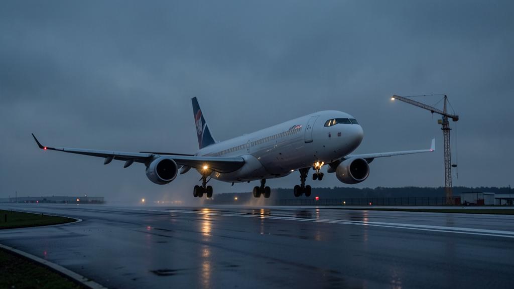
An obstacle does not matter because it is tall. It matters because of where it sits inside an area that opens out behind the aeroplane as the aeroplane climbs, and because of what the flight path is assumed to be doing when it passes. Three separate systems draw that area — one protects the aerodrome from construction, one designs the published departure, one sets the weight you can carry today — and they use different slopes, different widths and different assumptions about how many engines are running. Confusing them is how a departure that looks clear on the chart becomes a departure that is not.
Three obstacle systems sharing one runway
The single most common misreading in a departure briefing is treating the published standard instrument departure as an obstacle clearance guarantee. It is not, and it never claimed to be. Procedure design under the PANS-OPS assumes every engine is operating. The moment one stops, the procedure’s promise lapses and the responsibility moves to the operator’s own data.
| System | What it is for | Engines assumed | Who owns it |
|---|---|---|---|
| ICAO Annex 14 obstacle limitation surfaces | Safeguarding the aerodrome: what may be built and what must be reported or lit | Not a flight-path model at all | The aerodrome operator and the state |
| PANS-OPS departure procedure design | Drawing a published departure that a normally performing aeroplane can fly | All engines operating | The procedure designer, published in the AIP |
| Certification and Part-CAT net take-off flight path | Setting the maximum weight from which the obstacles can still be cleared after a failure | Critical engine inoperative from the failure speed | The operator, from manufacturer data |
The Annex 14 take-off climb surface is worth knowing precisely because its numbers look deceptively like the performance ones. For a runway serving larger aeroplanes it rises at two per cent, diverges at twelve and a half per cent on each side, and runs out to a fixed final width and length. That surface tells a planning authority whether a mast may be erected. It says nothing about whether your aeroplane clears the mast at today’s weight, and an obstacle that penetrates it is not automatically a problem for you — nor is an obstacle that respects it automatically harmless.
The published departure works from a procedure design gradient. Where nothing requires more, the default gradient carries a margin over the obstacle identification surface beneath it: the surface itself rises at two and a half per cent from a point just above the departure end of the runway, and the design gradient of three point three per cent puts eight tenths of a per cent of clearance above it. That margin is thin by design, and it is a margin against obstacles, not against a failure.
Where the flight path is deemed to begin
The take-off flight path used for obstacle work does not start at brake release. It starts at the end of the take-off distance, at the screen height — thirty-five feet above the surface on a dry runway, and fifteen feet on a wet one, because a wet-runway take-off distance is computed to a lower screen. Everything before that point belongs to the runway calculation; everything after belongs to the obstacle calculation, and the two meet at a single notional point that no aeroplane has ever flown through exactly.
The path is built on a failure at the engine failure speed, with the aeroplane continuing. It ends where the transition to the en-route configuration is complete and the final take-off speed has been reached, or at fifteen hundred feet above the take-off surface, whichever is higher. Between those two points, every obstacle inside the corridor has to be cleared by the net path.
Gross, net, and the gradient that is taken away
The gross flight path is what the aeroplane demonstrated. The net flight path is the gross path with a fixed gradient decrement applied throughout: eight tenths of a per cent for a two-engine aeroplane, nine tenths for a three-engine, one full per cent for a four-engine. Those decrements are not a pilot’s safety cushion and should never be flown as one. They exist because certification data is collected on new aeroplanes flown by test pilots, and the fleet in service is neither. The decrement converts a demonstrated performance into one that an average aeroplane, flown by an average crew on an average day, can be expected to achieve.
Two consequences follow. First, the gradient that clears an obstacle is never the one in the certification paragraph: it is the gross gradient the aeroplane achieves at today’s weight, minus the decrement. A twin sitting exactly on its two point four per cent floor is credited with one point six per cent, and a heavy departure is precisely where the gross gradient falls towards that floor. Second, the decrement grows with engine count, but so does the required minimum, so the credited second-segment figure still rises across two, three and four engines. Extra engines buy less margin on a limiting departure than the raw thrust arithmetic suggests, because part of what they add is taken back by the decrement.
The corridor that opens at twelve and a half per cent
An obstacle has to be cleared vertically by thirty-five feet, or laterally by enough distance that it is not in the way at all. The European rules express the second option as a horizontal distance that grows with the distance flown: a fixed initial half-width plus one eighth of the distance travelled from the end of the take-off distance available. That is the splay. It is why an obstacle five miles out at a given lateral offset can be irrelevant while the same obstacle at the same offset one mile out is limiting.
| Element | What the European rules use | Why it is there |
|---|---|---|
| Initial half-width | Ninety metres, or half the wingspan plus sixty metres for a span under sixty metres | Track-keeping error at low height, plus the aeroplane’s own width |
| Splay | One eighth — 12.5 per cent — of the distance flown from the end of the take-off distance available | Track error grows with distance flown, so the protected area must grow with it |
| Outer limit | A few hundred metres where the required navigational accuracy is held, roughly double where it is not, and larger again for a turning departure | Beyond that offset, an obstacle is no longer credibly on the flight path |
| First turn | Not before the net path reaches half the wingspan, and never below fifty feet above the end of the take-off run available | Below that, a bank puts a wingtip at risk before it costs any gradient |
| Bank scheduled | Fifteen degrees up to four hundred feet; above four hundred feet, up to twenty-five degrees may be scheduled | Below four hundred feet the speed margin and the height margin are both at their thinnest |
Read the last two rows together and the geometry of a turning departure becomes obvious. The turn cannot start early, the bank is capped while the aeroplane is low, and the corridor that protects it is wider — which sounds generous until you realise that a wider corridor means more obstacles inside it, not fewer. Every metre the corridor gains laterally is a metre of terrain that now has to be cleared by thirty-five feet on the net path.
The obstacle clearance area around a take-off path is like a cone that gets wider as the plane climbs. If you turn too early or too steeply, you lose climb performance and might not clear obstacles. The rules set limits on when and how much you can turn to keep the plane safe.
A Boeing 737-800 taking off from a runway with a 50-foot obstacle 1 mile away must clear it by at least 35 feet. If the net climb gradient is 1.6%, the plane must be at 51 feet (35 + 16 feet) at 1 mile. If the crew turns too early, the climb rate drops, and the plane might only reach 45 feet, failing to clear the obstacle.
The segments, and the one that usually sets the weight
| Segment | Configuration | Minimum gross gradient (two / three / four engines) | What ends it |
|---|---|---|---|
| First | Gear travelling, take-off flap, take-off thrust | Positive / 0.3 / 0.5 per cent | Landing gear fully retracted |
| Second | Gear up, take-off flap, climb speed held | 2.4 / 2.7 / 3.0 per cent | Level-off height, at or above four hundred feet |
| Third | Level acceleration, flaps retracting on schedule | No gradient — the energy goes into speed | En-route climb speed reached, aeroplane clean |
| Final | Clean, maximum continuous thrust | 1.2 / 1.5 / 1.7 per cent | Fifteen hundred feet, or transition complete |
The second segment sets the weight on most limiting departures, and it does so for a structural reason: it is the only segment that must both hold a gradient and clear obstacles while the aeroplane is still in a high-drag configuration with an asymmetric thrust penalty. The third segment is the one crews get wrong, because it is the one where the aeroplane stops climbing on purpose. Any obstacle that arrives during that acceleration has to be cleared by a path that is level, and if the level-off height was chosen against a shorter obstacle set than the one actually present, the acceleration has to be delayed — which costs time at take-off thrust and can run into the thrust time limit.
The trap A second segment flown at a slightly high speed feels better and climbs worse. The scheduled climb speed is close to the best-gradient speed for that configuration; flying faster trades gradient for rate, and gradient is the only currency an obstacle accepts.
What a turn costs, and where the number comes from
Everyone repeats that a turn costs climb gradient. The useful question is how much, and the arithmetic is worth doing once so that the order of magnitude stops being a mystery.

In a steady banked turn the load factor is the reciprocal of the cosine of the bank angle: about one point zero four at fifteen degrees, about one point one zero at twenty-five. Induced drag varies roughly with the square of the load factor, so induced drag rises by around seven per cent at fifteen degrees and by around twenty-two per cent at twenty-five. Near the climb speed with take-off flap and one engine out, induced drag is a large share of total drag — often around half — so total drag rises by something on the order of three to four per cent at fifteen degrees and ten per cent at twenty-five.
Climb gradient is excess thrust divided by weight. At a lift-to-drag ratio typical of that configuration, total drag is roughly a tenth of the weight, so a ten per cent rise in drag removes about one per cent of gradient. That is the shape of it: a fifteen-degree turn costs a fraction of a per cent, a twenty-five-degree turn costs of the order of one per cent — against a certified minimum of two point four and a net credit of one point six. A single twenty-five-degree turn can therefore consume more than half of what the aeroplane had left after the decrement.
| Mechanism | Why it happens | Order of magnitude |
|---|---|---|
| Induced drag rises with load factor | More lift is needed to support the same weight while turning | The dominant term; roughly one per cent of gradient at twenty-five degrees |
| Stall speed rises | It scales with the square root of the load factor | About two per cent at fifteen degrees, five at twenty-five — which is why an AFM may impose a speed increment |
| A speed increment costs more gradient | Flying above the best-gradient speed trades slope for rate | Small on its own, but it stacks on top of the drag penalty |
| Track distance grows | The aeroplane covers more ground for the same height gained | Moves obstacles deeper into a corridor that is widening at the same time |
None of that arithmetic is a substitute for the manufacturer’s data, and it should never be used to justify a weight. It is there so that when the performance software returns a lower weight for a turning departure than for a straight one, the difference is recognisable rather than mysterious.
One further detail contradicts a widespread habit. The engine-out climb gradients are not obtained wings-level with the ball centred: the certification test conditions allow a small bank towards the operating engine, because that is the attitude in which an asymmetric aeroplane is aerodynamically cleanest, and the flight manual procedure normally repeats it. A crew that flies the engine-out climb with the wings precisely level and the resulting sideslip accepted will not reproduce the book figure, and the shortfall arrives exactly where there is nothing to spare. How much bank to fly is an AFM item, not a rule of thumb.
The turn nobody published
Because the published departure assumes all engines, an operator flying from an obstacle-rich aerodrome needs its own engine-out procedure — a track, a level-off height and an acceleration point built on the net path rather than on the procedure design gradient. That procedure is the operator’s property. It is not in the AIP, the controller does not know it, and it frequently diverges from the published departure within the first few miles.
Two operational consequences follow directly. The divergence has to be briefed before departure, because the moment to decide it is not the moment the failure happens. And the deviation has to be declared as soon as workload allows, because from the ground the aeroplane is simply not where the clearance put it. Getting this right is one of the clearer markers of a well-run flight operations department, and it is a topic that recurs constantly in professional discussion on the FL330 forums.
The right reflex Brief the obstacle, not the gradient. A number on a chart tells you nothing you can act on; knowing that the limiting obstacle sits left of track at four miles tells you which side to keep the turn away from and why the level-off height is what it is.
Reading the limiting weight backwards
When performance software returns a limiting weight, it is answering one question: what is the heaviest this aeroplane can be and still put a net path above every obstacle inside the corridor, after a failure at the worst moment? Every input that widens the corridor, delays the turn, lowers the gradient or moves the level-off height changes that answer. Runway condition, wind component, temperature, bleed configuration, thrust rating and the departure track are not separate corrections applied to a number — they are the number.
Which is why the honest way to challenge a limiting weight is never to ask for a bigger number, but to ask which obstacle produced the small one. That obstacle has a position, a height and a distance, and once those are on the table the conversation about flap setting, thrust rating, improved climb or a different departure track becomes an engineering discussion instead of a negotiation.


Leave a Reply
You must be logged in to post a comment.