
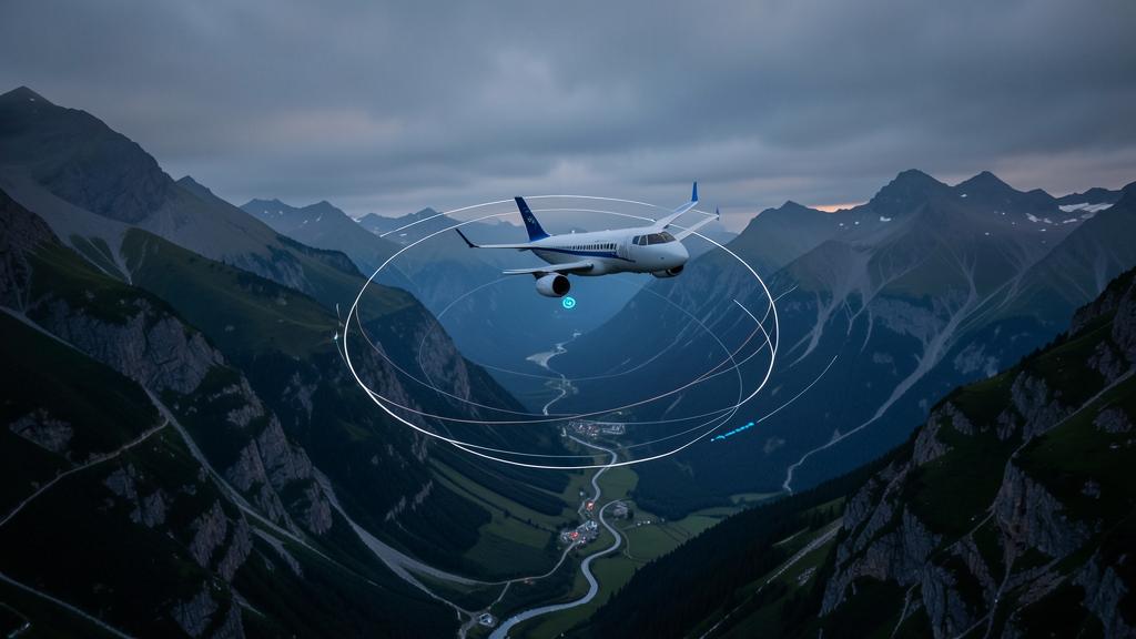
A radius-to-fix segment looks, on the chart, like a slightly prettier turn. It is not. Every other way of joining two tracks produces a ground path that depends on the day — on the wind, on the ground speed, on how much bank the autopilot happened to command. A constant-radius arc produces a ground path that was decided by the procedure designer and is the same in a thirty-knot tailwind as in still air. That single property is what allows a protection area to be drawn tight enough to fit inside a valley, and it is also why the capability is not universal: guaranteeing a curve costs the aeroplane something, and not every aeroplane can pay.
A turn whose ground track is a promise, not an outcome
Consider the ordinary case first. Two straight legs meet at a waypoint, and the aircraft flies a fly-by turn. The flight management system computes a turn anticipation distance from the current ground speed, the track change and its bank limit, starts the turn early, and rolls out on the next leg. The result is a curve, but nobody specified that curve. It emerged. Change the wind, the weight or the speed and the same coded procedure produces a measurably different path over the ground. Procedure designers know this, which is why the protection area around a conventional turn is generous: it has to contain every path the turn could plausibly produce.
A radius-to-fix leg inverts the logic. The database does not code two legs and a waypoint; it codes an arc — a terminating fix, a turn centre, a radius and a direction. The path is a geometric object that exists before the aircraft does. The aircraft’s job is no longer to produce a reasonable turn but to fly a defined curve, and the flight guidance achieves that by continuously varying bank against wind and ground speed so that the track over the ground stays on the arc.
This is the entire point, and it is worth stating plainly: an RF leg is not a more accurate turn. It is a turn whose ground track is specified rather than computed, which lets the designer shrink the protected airspace around it.
A radius-to-fix leg is a pre-planned curve that the aircraft must follow exactly, unlike a normal turn where the path changes with wind and speed. This allows for tighter safety zones, especially in tricky terrain.
An Airbus A320 flying a radius-to-fix approach to a mountainous airport must maintain a 2.5NM radius curve at exactly 150 knots. If it exceeds this speed, the required bank angle becomes too steep, and the aircraft may drift outside the protected area into terrain.
| Property | Fly-by turn | DME arc | Radius-to-fix leg |
|---|---|---|---|
| What defines the path | Turn anticipation computed from speed, bank limit and track change | A constant slant distance from a ground station | A fixed radius about a defined centre, terminating at a fix |
| Ground track repeatability | Varies with wind, weight and speed | Reasonably repeatable, but flown as a series of corrections | Specified in the procedure design and held by the guidance |
| Reference used | Area navigation position | A specific navaid, which must be serviceable and in range | Area navigation position, station-independent |
| Protection area | Generous, because it must contain every plausible path | Moderate, tied to the station’s geometry | Narrow, which is why it can be used against terrain |
| Aircraft capability needed | Universal in area navigation systems | Basic, with the appropriate receiver | Specific: the path terminator, the guidance and the approval |
Two guarantees that are constantly confused
Before going further it is worth separating two things that appear together on the same charts and answer different questions. RF describes the shape of the intended path. RNP describes how far from that path the aircraft may be. They are independent statements, and an aircraft can satisfy one without the other.
Required navigation performance is a containment and alerting requirement: the system must keep lateral deviation within a stated value for a stated proportion of flight time, and it must tell the crew when it can no longer be confident of doing so. That is on-board performance monitoring and alerting, and it is the property that distinguishes an RNP specification from a plain area-navigation one. The radius-to-fix leg is a different kind of thing altogether — it is a function, one of a list of capabilities that a navigation specification may require or permit. This is why the eligibility statement in an aeroplane flight manual reads as a specification plus a list of functions rather than a single label, and why « we are RNP approved » answers nothing on its own. The question is always which specification, with which functions.
What the flight management system must actually be able to do
Three separate pieces of the aeroplane have to cooperate before a curved line on a chart becomes a curved line over the ground, and a shortfall in any one of them removes the capability.
The navigation database and the flight management computer must support the path terminator itself. This is not a matter of degree. A system that does not recognise the coding does not fly an approximation of the arc; it rejects the procedure, or the procedure is simply not offered in that airframe’s database. There is no graceful degradation available, and this is a common reason an operator finds that half its fleet can use an approach and the other half cannot.
The flight guidance must be able to command and hold the roll attitude the arc demands, continuously, in roll-steering. A flight director that can follow a track is not automatically a flight director that can hold a radius against a changing wind vector. The authority, the bank limits in the relevant mode and the behaviour at the roll-in and roll-out points are all type-specific and are all stated by the manufacturer.
The navigation sensor and position solution must support the required performance throughout, which in practice means a satellite-based position with the appropriate integrity, and for the more demanding applications a level of redundancy that lets the aircraft continue if one element fails at the least convenient moment.
The geometry: radius, ground speed and bank
The reason the capability has limits is not electronic. It is mechanical, and it comes from one relationship. In a coordinated level turn the radius, the ground speed and the bank angle are tied together: the radius varies as the square of the speed and inversely with the tangent of the bank angle. Written the other way round, the bank required to hold a given radius rises steeply with ground speed.
Everything operationally important about RF legs follows from that sentence. The radius is fixed by the procedure. The bank angle available is bounded by the flight guidance, by the design criteria and by what is acceptable near the ground with passengers aboard. Therefore the only free variable left is speed, and that is why RF procedures carry published speed restrictions and why those restrictions are not advisory comfort limits. Exceeding the speed on an arc does not make the turn less tidy. It makes the arc unflyable within the available bank, and the aircraft departs the protected area on the outside of the curve — which, in the geometry these procedures were invented for, is the side with the terrain on it.
The trap. Treating the arc speed as a target rather than a limit, and arriving at the roll-in point fast because the previous segment was flown with speed intervention or a late descent. The bank margin is consumed before the turn begins, and the first indication is usually the aircraft going wide at the point of maximum track change. Speed is stabilised before the arc, not on it.
The speed limit on a radius-to-fix approach is not a suggestion—it’s a hard limit. If you fly too fast, the required bank angle becomes too steep, and the aircraft may drift into terrain.
A Boeing 737 flying a 3NM radius-to-fix approach at 180 knots instead of the required 160 knots would need a 35° bank angle to stay on the curve. If the aircraft’s maximum bank is 30°, it will drift outside the protected area, risking a controlled flight into terrain (CFIT).
What eats the bank margin
The design of the procedure assumes bounded conditions. Several ordinary operational factors push toward the boundary at once, and they tend to arrive together rather than separately.
| Factor | Effect on the arc | Where the bound is set |
|---|---|---|
| Tailwind component during the turn | Raises ground speed on part of the arc, so the bank demand rises there | The wind assumptions in the design criteria and the operator’s own wind limits |
| High aerodrome elevation or high temperature | Higher true airspeed for the same indicated speed, therefore higher ground speed | The procedure’s speed restriction and any temperature limitation on the approach |
| Flying faster than the published arc speed | Bank demand rises with the square of speed — the dominant term | The chart, and it is a limit rather than a suggestion |
| Reduced bank limits in the active guidance mode | Less bank available than the airframe could physically use | The aeroplane flight manual and the type’s mode logic |
| Ice accretion procedures and their speed additives | Higher minimum speeds and, on some types, reduced bank | The type’s icing procedures, which may make an arc unavailable |
| Late configuration or an unstabilised entry | Speed still decaying at roll-in, so the guidance chases the arc from behind | The operator’s stabilised approach criteria, applied before the arc |
Read together, these explain why an approach that is routine in winter at sea level can be unavailable on a hot afternoon at altitude with a tailwind on the arc, for the same aircraft flown by the same crew. Nothing has been downgraded. The geometry simply ran out of bank.
The autopilot requirement, and what happens when guidance drops
Because holding an arc against a varying wind is a continuous roll-modulation task rather than a tracking task, many approvals require the autopilot engaged, or at minimum a coupled flight director, for the segments containing RF legs. Which of the two is acceptable, and down to what point, is a statement in the aeroplane flight manual and in the operational approval — it is not a general rule, and it is one of the places where types and authorities genuinely differ.
The corollary is the case that must be briefed rather than discovered: an autopilot disconnect on the arc. The aircraft has not lost the path — the guidance is still computing it and the flight director is still showing it — but the crew has just inherited a continuously varying bank demand at low altitude in a place chosen for its terrain. The correct response is a briefing item on every RF procedure, and on many operations the answer is a discontinuance rather than a hand-flown arc.
The right reflex. Brief the arc by its three failure points rather than by its shape: the entry speed and where it is stabilised, what is done if the autopilot drops on the arc, and which mode selections would delete the leg. A briefing that describes the curve tells the other pilot nothing they cannot read from the chart.
Where an RF leg is lost, and how
An RF leg is a coded object in an active flight plan. Anything that removes it from the active flight plan removes the guarantee, immediately and without any indication that the aircraft is now outside a protected area rather than inside one.
Selecting heading or track mode replaces the arc with a straight line from wherever the aircraft happens to be. A direct-to entry discards the arc and substitutes a great-circle track to the target fix, which in a valley procedure can point directly at the wall the arc was drawn to avoid. A vectoring instruction accepted mid-arc does the same thing by a different route. And on several types a go-around initiated on the arc changes the lateral mode in a way that requires deliberate re-engagement of the managed lateral mode — which is why the missed approach, if it contains RF legs of its own, deserves the same attention as the approach.
None of this is exotic; it is the ordinary behaviour of a flight management system. What makes it consequential here is that on every other kind of procedure, leaving the coded path costs accuracy, whereas on an RF leg in a terrain-constrained procedure it costs the containment that justified the procedure’s existence.
The approval chain behind one curved line
The reason a capable aircraft still cannot fly a given procedure is that aircraft capability is only one layer of several, and all of them must be satisfied simultaneously.
| Layer | What must hold | Where it is written |
|---|---|---|
| Procedure design | The arc, its radius, its speed limits and its protection area are constructed to the applicable criteria | The State’s procedure design rules, built on the ICAO PANS-OPS criteria |
| Aircraft eligibility | The navigation specification and the functions supported, including the RF path terminator | The aeroplane flight manual and the manufacturer’s operational documentation |
| Navigation data | The procedure is coded in the database, from a supplier working to a recognised data-quality process | The data supplier’s acceptance and the operator’s data management procedures |
| Operational approval | An authorisation covering the specification and, for the more demanding applications, a specific approval | EASA specific approvals under Part-SPA; the FAA route runs through operations specifications instead |
| Crew qualification | Training and checking on the procedure type, its mode management and its failure cases | The operator’s training programme, approved by the authority |
| Continued monitoring | Deviation monitoring and reporting, so that degradation is detected rather than assumed absent | The operator’s management system and the conditions of the approval |
Why this shapes access to whole airports
The practical result is that constant-radius geometry is the technology that opens terrain-constrained aerodromes, curved noise-abatement departures and closely spaced parallel or converging operations. It does so by replacing a wide protected corridor with a narrow one, and a narrow corridor is only safe if the aircraft inside it is genuinely bound to the curve.

For an operator this converts a technical detail into a fleet planning problem. Two subfleets that look interchangeable on paper can differ in whether they may use the approach that makes a destination viable in poor weather, and the fix is not a procedure change but a retrofit — a flight management system standard, an updated flight manual, a new approval and a training package. That is a budget line and a schedule, not an option selection. Crews comparing how their operators handle RF entry speeds, autopilot loss and missed approaches will find the topic covered in the performance and navigation material at FL330 training, but the type-specific answers only ever come from the manufacturer’s documentation.
The useful mental model to carry away is the one the procedure designer used. The arc is not there because a curve is elegant. It is there because a guaranteed ground track is what lets the corridor through a turn be drawn narrow, and the aircraft that may fly it are exactly those that can guarantee it — at that speed, with that wind, with that much bank in hand.


Leave a Reply
You must be logged in to post a comment.