
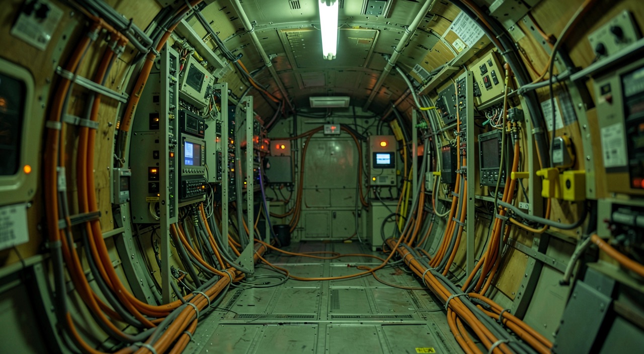
A test aircraft takes off heavier than any production model: a probe extending far ahead of the nose, instrumentation racks bolted where seats should be, harnesses running along the floor, water barrels transferred in flight to sweep the center of gravity range. However, the takeoff distances in the flight manual do not come from this aircraft. They come from a calculation that subtracts everything the installation added, then transposes the result to conditions that no one encountered in flight that day. Knowing what was subtracted—and especially what was not—explains much of the discrepancies observed later in service.
What flies is not what is certified
Certification applies to a type, not the test aircraft. The test aircraft is a means to achieve certification, not the certified product itself. Between them lies an installation that modifies the aircraft’s characteristics just like any other modification (winglets, cabin arrangements, etc.).
It is conveniently divided into four families. First, the sensors: pressure ports, thermocouples, accelerometers, angle of attack and sideslip probes, control surface position sensors, control column and rudder pedals dynamometers, strain gauges glued to the spars. Then, the acquisition chain: conditioning, filtering, digitization, timestamping, recording. Telemetry, which exports some of these channels to the ground in real time and requires a transmitter, antennas, and electrical power. Finally, the specific safety means: spin-recovery parachutes, jettisonable ballast, emergency hatch, dedicated cutouts, not to mention the cameras, tufts of wool, and smoke generators that make visible what the sensors do not quantify.
Each component adds weight, drag, and measurement distortion. A flight test consists as much of producing measurement points as of knowing, station by station, what the installation did to the aircraft that produced them.
The test aircraft is not the same as the production model. Engineers add sensors and equipment that change how the plane flies. They then subtract these changes mathematically to get the real performance numbers. If they miss something, the flight manual numbers might be wrong later.
On an Airbus A320 test campaign, 300 meters of cables added 15 kg of weight with a significant aft center of gravity effect. The pitot probe added 3 kg at the nose but created drag equivalent to 5% of the aircraft’s total drag at high speeds. Engineers had to carefully account for these changes to get accurate takeoff distance calculations.
The test mass budget and the weight of a cable
The test aircraft has its own mass and balance. The first consequence is arithmetic. The test aircraft has its own empty weight, its own empty center of gravity, and a mass budget unrelated to the production model. The racks are weighed, but the surprise is not there: it is the wiring. The accumulated length of the harnesses is usually hundreds of meters; including cable trays and fasteners, it runs from front to rear, often as close to the floor as possible, i.e., far from the reference center of gravity. All this usually weighs tens of kilograms, and its moment is never neutral.
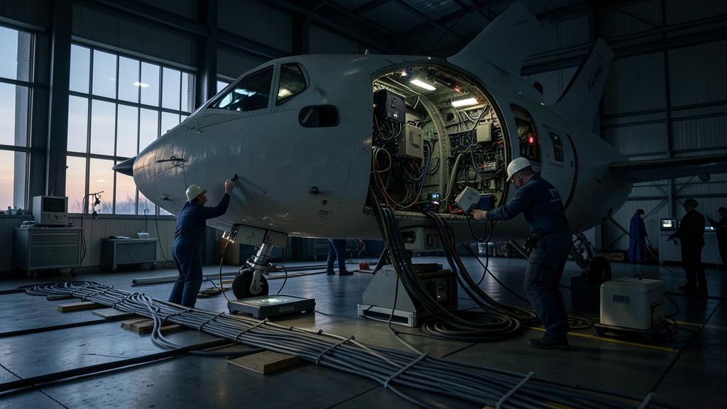
Reinforcements modify structural behavior. Add the reinforcements. An instrumentation rack is not installed on the seat rails without load redistribution, a probe is not attached to a nose without fittings. These reinforcements locally modify the stiffness, therefore the natural frequencies and the aeroelastic couplings that the campaign is precisely tasked with exploring. The installation intended to observe the phenomenon participates in the phenomenon.
Ballast compensates for installation effects. Then there is the ballast, the only element deliberately added. The demonstration requires reaching the corners of the domain: forward center of gravity toward high mass, where the elevator must still allow the flare; aft center of gravity, where stability and behavior at the onset of stall are more critical. However, the instrumented aircraft is spontaneously heavier than the production model and, often, more aft, because the racks occupy the cabin and the telemetry is generally housed toward the rear. The ballast—ingots in the baggage hold, transferable water barrels between tanks in flight—retrieves the corners that the installation had made inaccessible. Transferable, it also allows sweeping several centers of gravity without landing between points.
Mass budget is a living document. Any significant modification of the installation requires a new weighing. The test mass budget is a living document, maintained at the sensor level, because each performance point will later be referenced to a mass and a center of gravity: an error in the budget propagates intact to the flight manual’s chart.
| Installation station | Mass and centering | Aerodynamic effect | How it is subtracted |
|---|---|---|---|
| Instrumentation racks, computers, recorders | Mass weighed and concentrated in the cabin, marked aft effect | None | Test mass budget, then recalibrated to the reference mass and centering |
| Harnesses and cable trays | Diffuse mass from front to rear, regularly underestimated moment | None | Weighing after each significant modification of the installation |
| Pitot probe, probes, trailing cone | Modest mass but very forward or very aft, therefore strong lever arm | Added drag, increasing with Mach number | Installation drag model, calibrated by flights with and without when possible |
| Pressure port belts, antennas, cameras | Low mass, distributed | Steps in the boundary layer, local separations | Measured increase in compared configurations, supported by wind tunnel and calculation |
| Ballast: ingots in the baggage hold, transferable water | Deliberately added, to reach the corners of the domain | None | Not subtracted: it is part of the declared test condition |
The installation that modifies the airflow
The pitot probe changes airflow characteristics. The pitot probe is the most visible and most misunderstood component. It does not measure better by principle: it carries the pressure ports and probes ahead of the pressure field that the aircraft creates around itself, where the disturbance is low and, above all, modelable. It has a cost: a drag, a cantilevered mass, and a natural mode that belongs to it, which must be remembered is not that of the aircraft.
Each sensor creates its own disturbances. The trailing cone follows the same logic on the other side: a tube deployed behind the tail, stabilized by a cone, seeks a static pressure in the air that the aircraft has not yet disturbed, at the cost of a drag, a long pneumatic response time, and a restricted domain of use. To this are added the pressure port belts glued along the fuselage, which create as many steps in the boundary layer, the telemetry antennas, the camera pods, and, in spin tests, the parachute with its anchoring structure.
Drag increases non-linearly with speed. The conclusion is simple to state and costly to ignore: the polar of the instrumented aircraft is not that of the production model, and the gap is not constant. An excrescence that costs almost nothing at low speed can, in the upper part of the domain, develop a local supersonic zone and a shock wave; the drag increase no longer follows the speed wisely and takes off. A fixed correction, calibrated halfway, overestimates the penalty on one side and underestimates it on the other, which is the best way to be wrong twice.
The trap: the installation that improves the aircraft. One instinctively reasons as if instrumentation could only penalize, and one always corrects in the same direction. This is false more often than one thinks. A probe moves the static port out of an unfavorable pressure field and eliminates an error that the production model, on its side, will retain. A rack installation stiffens a floor and dampens a mode that, without it, would have manifested itself. An antenna fairing reattaches a local separation. The test aircraft then behaves better than the production model, the correction goes in the wrong direction, and the gap only reveals itself after entry into service. An installation is evaluated in both directions, never by default of penalty.
Anemometry, or measuring the measurement
Static ports don’t read free air pressure. No static port installed on a fuselage reads the static pressure of free air. The aircraft carries its own pressure field; at the port location, this field adds or subtracts something. This is not a manufacturing defect, it is a characteristic: it depends on the angle of attack, therefore the lift coefficient, therefore the mass and the load factor, as well as the configuration, the Mach number, and the sideslip. The static source error is mapped, then compensated in the air data computer.
Multiple references are needed for calibration. Mapping it requires an external reference, and no reference covers everything. The trailing cone provides one, on board and available over a large part of the domain. Passing at low altitude in front of a ground reference instrument provides another, precise but confined to the vicinity of the ground. A chase aircraft already calibrated carries the reference to the desired altitude, inheriting its uncertainty. Satellite positioning, flown on reciprocal legs intended to eliminate the wind, finally gives a true airspeed independent of any pressure, but says nothing about the static pressure without a temperature assumption. The results partially overlap, and it is this overlap that builds confidence.
Temperature probes have their own errors. Temperature undergoes the same treatment. A total temperature probe does not read the static temperature of the air: it reads a fraction of the increase in total temperature, and this recovery factor is calibrated before hoping for a usable static temperature. The entire pneumatic chain also has a response time: the length of the tubes, the dead volume, and the altitude extend the time constant. In a slow maneuver, this is not visible. In a climb, a deceleration, or an approach to stall, the altitude and speed traces lag behind the actual movement.
| Method | What it provides | Natural domain | Its limit |
|---|---|---|---|
| Drag cone | A static pressure taken outside the aircraft’s pressure field | Wide, from the bottom to the top of the domain | Own drag and response time, restrictive deployment |
| Low-altitude pass in front of an instrumented ground reference point | A known altitude and pressure reference independent of the aircraft | Near the ground, restricted speed window | Says nothing about the upper part of the domain, dependent on the atmospheric stability of the day |
| Already calibrated chase aircraft | The reference transported to the desired altitude and speed | Where stabilized formation flight is practicable | Total inheritance of the chase aircraft’s uncertainty |
| Satellite positioning, reciprocal legs | A true airspeed independent of any pressure measurement | Wide, even far from any ground installation | Assumes a stable wind during the legs and a temperature assumption |
Data reduction: two operations, not one
Two distinct processing steps exist. The two processing steps are regularly confused. The first subtracts the installation: added drag, actual mass and center of gravity of the day, static source error, chain delays. At the end of this step, the defined behavior of the aircraft is obtained, as it behaved that day, at that mass, altitude, and wind.
Transposition uses dimensionless coefficients. The second transposes. Each point is referenced to standard conditions: standard atmosphere, reference mass and center of gravity, zero wind, horizontal and dry runway, reference engine regime. The transposition is not done by rule of three, but by switching to dimensionless quantities: aerodynamic coefficients on one side, engine parameters corrected for inlet pressure and temperature on the other. This transition allows a few flown points to cover an entire domain, and that is what makes the test profitable.
Flight manual numbers are model outputs, not raw data. What the flight manual publishes is never a measured point: it is the output of a model that the points have calibrated. The consequence deserves to be stated frankly. The model is only valid in the domain where it was anchored, and the announced uncertainty is not that of a sensor, but of an entire chain: sensor, calibration, installation correction, piloting dispersion, transposition. This is also what allows the analysis to replace certain tests. Where the model is anchored on both sides, interpolation is legitimate; beyond the last flown point, there is only extrapolation that bears the name of a test.
The bias that the chain itself creates
Each measurement step adds its own errors. Between the phenomenon and the file, there is a sensor, a conditioner, a filter, a converter, a clock, sometimes a transmitter and a receiver. Each step has a gain, an offset, and a phase, and each one drifts in its own way.
Zero offsets are temperature-sensitive. The zero offset is the most common and the most pernicious, because it depends on temperature and temperature, in flight, changes a lot. Hence the rule of the trade: a zero taken before the flight and a zero taken after the flight frame the test, their difference measures the drift, and a significant drift disqualifies the point rather than being corrected. Calibration poses the symmetrical problem: a sensor chosen to cover the entire possible range resolves small variations poorly, precisely those that one is trying to see. Each test has its calibration, and changing the calibration changes the sensors.
Phase shifts create false measurements. However, the most costly bias is not visible in any channel taken individually. An anti-aliasing filter delays; two channels equipped with different filters do not delay for the same duration; a pneumatic channel delays differently. As long as the channels are read separately, nothing goes wrong. As soon as two are combined—a coefficient, a derivative, a control surface position related to an acceleration—the phase shift becomes an apparent physical effect. One believes to measure a mode damping; one measures a wiring delay. And nothing in the trace signals the deception.
The good reflex: make the offset a measured quantity, not an assumption. Before exploiting the combined channels, trigger a sharp front that all chains see at the same instant: a timestamp pulse, a clean shock on the structure, a square-wave command. Note in the recording the proper delay of each channel and subtract it. The known delay is corrected; the assumed delay is paid in results. The same reflex applies when reading a test report: ask on what time base the channels were realigned before discussing the conclusion.
What reaches operations
Flight manual numbers are conservative estimates. At the end of the chain, the operator receives charts and tables. They are corrected, standardized, then affected by factors and rounded in the conservative direction. That is why a crew never finds the flight manual numbers matched: these numbers describe a new airframe, an engine at reference rating, a demonstrated and not average piloting technique, and a runway whose condition corresponds to a definition, not to what is seen through the window.
Operators must verify reference conditions. What must be verified in the documentation itself is limited to a few lines, and these are rarely the ones read. The reference conditions under each chart, first: mass, center of gravity, configuration, air bleed, anti-icing, surface condition. The distinction between gross and net data next, which is not a vocabulary nuance, but an applied factor. The origin of the operational numbers finally: do they come from the approved flight manual, or from a performance software that carries its own model and transposition assumptions? And above all the degradation factor attached to the aircraft registration, derived from fuel consumption monitoring, the only piece of the chain that the operator produces on their own.
Certification doesn’t cover individual aircraft. The gray area is there, and it will not close: certification applies to a type, operations are conducted on an individual airframe. Between them lies an individual gap that no one measured during the tests and that only in-service monitoring informs. For those preparing a type rating or processing an approval file, the useful reading is not the number in the middle of the chart: it is the line of conditions written below, and the question of which of these conditions the flight of the day does not meet. This is also the angle from which performance training courses distinguish themselves from each other.
The applicable text, the approved flight manual, and the approved operational documentation prevail over this article, whose purpose is limited to explaining a mechanism.


Leave a Reply
You must be logged in to post a comment.