
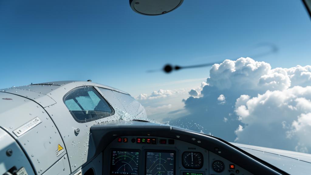
Cruise at FL 350, clear skies ahead, a line of cumulonimbus clouds bypassed to the right and left behind for eight minutes, radar clear for eighty nautical miles. Then three seconds of gravel noise on the radome. At the parking stand, the nose is pitted and the horizontal stabilizer’s leading edge is marked. None of this appeared on the screen, and none of this is abnormal: hail that hits transport aircraft in cruise almost never exits the core of the airframe. It exits from its anvil, downwind, in clear air.
The onboard radar measures liquid water, not danger.
A weather radar, almost always in X-band on transport aircraft, does not detect a cloud: it detects targets large enough to return a usable signal. In the scattering regime applicable to raindrops, the backscattered power varies as the sixth power of the target’s diameter, and proportionally to a dielectric factor that depends on the medium’s nature. This factor is about five times lower for ice than for liquid water. At equal volume, a dry hailstone returns a fraction of what a raindrop does, and an anvil crystal, whose diameter is measured in tens of micrometers, never crosses the display threshold.
The consequence deserves to be stated bluntly: the screen does not show where the danger is, it shows where the rain is. The anvil, which is a volume of ice several tens of miles long, displays as black. The hail that crosses it as it falls remains dry until it is above the zero-isotherm, so it also displays as black. The only time a hailstone becomes clearly visible is when it melts and is covered with a film of water: it then backscatters like a raindrop of its own diameter, producing the violently saturated echoes seen in the lower layers. At this stage, the information arrives several thousand feet below the cruise level.
The radar only detects liquid water, not ice. Hailstones are invisible until they melt, so the screen shows rain, not danger. The real threat comes from dry hail falling in clear air downwind.
An Airbus A320 at FL370 encounters hail 50nm downwind of a cumulonimbus cell. The radar shows no echoes, but the aircraft suffers damage to the radome and leading edges. The hailstones, 1-2cm in diameter, fell from the anvil in clear air, undetected by the radar.
Attenuation digs a second hole.
The X-band is strongly absorbed by the rain it passes through. Behind an intense core, the beam emerges weakened, and the radar paints a dark zone that is not clear air but ignorance. This shadow extends exactly along the line of sight, therefore behind the cell being bypassed — and often, by geometric construction, on the side toward which one wants to cut. Two different causes thus produce the same absence of echo on the same side, and neither means the passage is clear.
How a hailstone leaves the cloud.
A hailstone does not grow as it falls. It grows while being carried. In the layer where supercooled water coexists with ice, typically between the -10°C and -30°C isotherms, an embryo captures droplets that freeze on contact and deposit in successive layers. As long as the updraft speed exceeds its fall speed, it remains in the « factory. » It exits when one of the two terms ceases to dominate: either it has become too heavy, or it has been ejected from the most vigorous part of the current.
It is the wind shear that decides the outcome. In an atmosphere where the wind turns and strengthens with altitude, the updraft is inclined: its base and top are not vertical to each other. A hydrometeor that rises therefore drifts laterally, and it exits the current from the downwind flank. At the top, under the stable layer capping the troposphere, the column can no longer rise: it diverges horizontally and spreads out. This is the anvil, and it is a conveyor belt. Everything that has been carried there — crystals, aggregates, hailstones — is deposited and carried away by the high-altitude flow.
Part of the anvil moves upwind rather than following the wind: the upstream edge then appears upright and sharp, as if sculpted against the current. This is not a shape oddity, it is an intensity indicator. An anvil that can spread against the flow signals an updraft capable of overcoming that flow, hence a cell that manufactures and exports hail in large quantities. The same reasoning applies to a penetrating top, that dome that briefly pierces above the spreading level.
The arithmetic of the fall explains the asymmetry.
Once out of the current, a hailstone has only a ballistic trajectory corrected by the wind: it falls at its terminal velocity and drifts at the speed of the surrounding air. The orders of magnitude are sufficient to understand the rest. A centimeter-sized hailstone falls at around fifteen to twenty meters per second; a hailstone of a few millimeters, twice as slow. At the anvil level, the flow is commonly measured in tens of knots, sometimes in hundreds when the cell is attached to a jet stream.
Multiply: the smaller the hailstone, the longer it takes to descend, and the farther the wind carries it. The large ones fall near the core, in the area that the radar paints in red and that no one voluntarily crosses. The small ones reach distances measured in tens of kilometers, and they arrive in perfectly clear air. This is exactly the opposite of the intuition that places the biggest dangers far away and the smallest ones near. Hail encountered in cruise is almost always small hail, and it is almost always downwind.
The modest caliber does not reassure for long, because it is not the hailstone that brings the energy. The impact energy varies as the square of the closing speed, and this is almost entirely due to the aircraft. At cruise speed, a one-centimeter hailstone delivers energy on the order of tens of joules, the equivalent of a kilogram dropped from one meter — and it never arrives alone.
The rule of uniform distance and what it misses.
The lateral margin of about twenty nautical miles retained by many operating manuals at medium and high levels is a good rule, for a bad reason: it is easy to maintain under pressure. But it is isotropic, while the phenomenon is not. Twenty miles upwind of a mature cell is a comfortable margin, almost a luxury. Twenty miles downwind, under an anvil whose spread is several times that distance, is a margin that protects from nothing.
| Sector relative to the cell | What the screen shows | Dominant hazard | Conduite |
|---|---|---|---|
| Upwind, upstream of the upper-level flow | Tight gradient, sharp echo edge | Edge turbulence, entry shear | Nominal manual margin, held firmly |
| Abeam | Strong echo, clear outline | Flank updraught, icing on descent | Nominal margin, without cutting it in turns |
| Downwind, under the anvil | Black, or a few scattered echoes with no structure | Hail in clear air, turbulence, lightning strike | Increased margin, and preferably no passage |
| Above the apparent top | Top systematically underestimated | Overshooting top, anvil growing vertically | Overflight to be avoided whenever the vertical margin is not clear-cut |
| In line, behind an intense core | Dark path-attenuation zone | Cell completely masked | Never read this zone as a clear passage |
The trap: the darkest side of the screen is almost always the downwind side. The anvil returns nothing, the dry hail returns nothing, and the path attenuation adds its shadow as soon as you look through the core. Three independent causes produce the same absence of echo in the same place. A bypass chosen solely on screen color therefore systematically leads to the wrong side, and the radar’s silence is then interpreted as confirmation.
Reading the radar differently: site, gain, echo height.
If the screen cannot show the hail, it can show the machine that produces it. This requires abandoning the passive use of the radar — antenna at automatic tilt, calibrated gain, single horizontal plane — to interrogate it in volume. The question to ask is not « where is the rain » but « to what altitude does this cell hold water. »
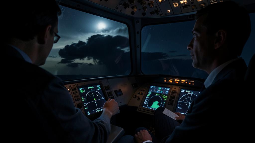
An updraft that maintains a strong echo well above the melting level transports supercooled water to altitudes where it should no longer exist. This is the signature of a powerful vertical current, hence an operational hail factory, and this signature is readable from the cockpit even though the hail itself will never be. Manual gain plays the same role on the horizontal plane: by reducing it, you erase weak echoes and reveal the exact position of the steepest gradient, i.e., the real core rather than the smoothed spot that the automatic mode has produced.
| Action on the control panel | What it reveals | What it still does not reveal |
|---|---|---|
| Tilt lowered towards the core | The maximum intensity of liquid precipitation and the position of the core | The ice content above the freezing level |
| Tilt raised above the freezing level | An echo that persists at altitude, hence an updraught capable of carrying large hydrometeors | Hailstones already ejected from the updraught, a few miles away |
| Gain set to manual, then reduced | The tightest gradient, hence the real core rather than the smoothed blob | The anvil, invisible at any gain setting |
| Volumetric scan and vertical profile | The shape of the top, the echo height, the presence of an overshooting dome | What lies behind an already attenuated area |
Volumetric scanning installations, which build a three-dimensional image in memory rather than a single plane, reduce the workload but do not change the physics: they offer probable hail or probable lightning depictions that are inferences from the structure of the liquid echo, not measurements of ice. The difference has a practical consequence: these depictions are good for identifying a dangerous cell, but bad for delimiting the downstream extent of what it has already exported.
The right reflex: before starting a bypass, read the wind at the flight level on the appropriate page of the flight management system — not the ground wind from the situation map, not the drift of the previous trajectory. The side from which this wind comes is the clean side. Announce it at the same time as the heading: « we’re passing to the left, it’s the upwind side. » A decision stated with its reason holds; a decision stated without reason is renegotiated with each new echo.
What the cell endures, and what the crew does next.
The impacts are distributed over the frontal surfaces: radome, wing and tailplane leading edges, engine inlet lips, windshield, antennas. The radome is the most exposed and the least robust, since its transparency to waves prevents it from being armored. Its degradation has a perverse consequence: it occurs at the precise moment when the radar would be most needed, and it can manifest as a degraded image before becoming a complete failure — hence an image that one continues to believe.
On the engine inlet lips, a bulge modifies the geometry of the captured flow and can manifest as vibrations, engine parameter variations, or pumping. On the leading edges, a deformed profile shifts the stall and drag characteristics, which is paid for during landing rather than in cruise. On the windshield, a cracked outer layer requires considering the differential pressure and therefore, possibly, the flight level.
Immediate handling consists of a few actions and a lot of discipline. Reducing to turbulence penetration speed divides the impact energy much faster than it lengthens the exposure time, since this energy varies as the square of the speed. Leaving the area by the shortest path, which almost always means returning upstream rather than continuing straight under the anvil. Not climbing: you climb toward the source. And considering that the flight now continues without a reliable radar, which changes the strategy for the rest of the thunderstorm line, not just the next ten minutes.
What remains to be decided before the next thunderstorm line.
Three checks are worth making in your own documentation, because the answers vary from one operator to another and none are obvious. First, is the prescribed lateral margin given as a single number or as a number with a downwind expansion clause? Next, is the overflight of cumulonimbus allowed, and at what vertical margin above the observed top — many manuals have abandoned it altogether for public transport. Finally, what speed does the manual specify in case of hail encounter, and where is it listed: in the turbulence procedure, in a separate procedure, or nowhere.
The gray area, however, will not be closed by documentation. No onboard sensor measures dry ice; everything displayed as « probable hail » is an inference from something else. The means that actually see the anvil and its extent — satellite imagery in the infrared, lightning detection networks, dual-polarization ground radar imagery — operate at rates and on media that are not those of the cockpit. Bridging this gap today falls under ground preparation and dialogue with ATC and operations, not an antenna adjustment.
For those preparing for a type rating or a line check, the subject is an excellent revealer: the question « which side do you bypass? » is poorly answered with a number and well answered with reasoning. It belongs to the same family as reading a significant weather chart or managing a weather diversion, and it is usefully practiced in theoretical and practical preparation before encountering it in line. The experience feedback shared on the crew exchanges forums shows, moreover, that the encounter in clear air surprises mainly those who had never formulated the mechanism, rarely those who had formulated it once.
The applicable requirements, the manual’s procedures, and the operator’s approved documentation prevail in all circumstances over this article, which is only explanatory in nature.


Leave a Reply
You must be logged in to post a comment.