
Ask where the boundary lies between a fuel cell chain and a hydrogen-burning turbine and the answer usually comes back as a power figure, as if there were a horsepower number above which one architecture stops working. There is no such number. The boundary is drawn by three quantities that behave very differently as size grows: the efficiency you actually achieve at the point that sizes the design, the heat you then have to move across a wall instead of out of a nozzle, and the mass of the hardware that moves it. Follow those three and the crossover appears on its own, in a place that depends as much on the mission as on the power rating.
The question is badly posed as « which is more efficient »
A low-temperature proton-exchange-membrane stack converts something in the region of half to sixty per cent of the hydrogen’s lower heating value into electrical work, depending on where it is run on its polarisation curve. A modern gas turbine core reaches thermal efficiencies of the same broad order, with the balance leaving in a hot exhaust. On a single-number comparison the fuel cell is usually the better of the two at cruise.
That comparison is close to meaningless for aircraft design. First, the fuel cell’s electrical output still has to become thrust: a converter, an inverter, a motor and a gearbox each take their cut, and the product of four efficiencies in the mid-nineties is noticeably less than any one of them. Second, and more important, efficiency tells you how large the losses are, not what they cost. What they cost depends entirely on the route by which they leave the aircraft.
Two ways to get rid of the same waste heat
This is the structural difference, and everything else is a consequence of it.
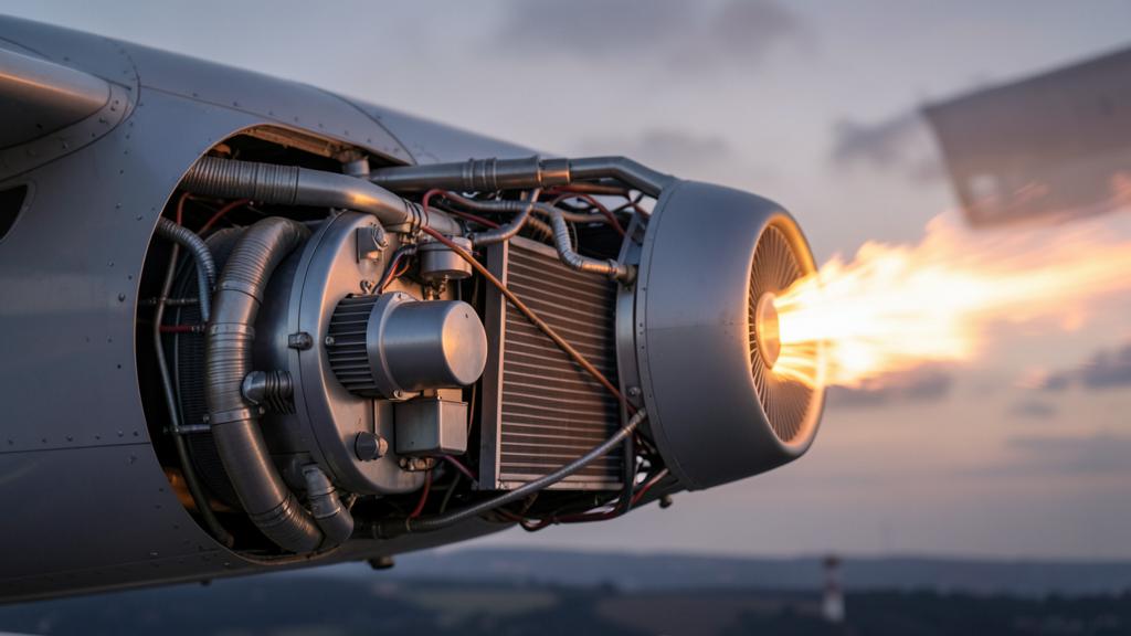
In a turbine, the waste heat leaves inside the working fluid: the gas heated in the combustor expands through the turbine, exits through the nozzle and takes the unconverted energy with it. No heat exchanger is involved. The rejection hardware weighs nothing because there is none — the exhaust is the rejection system, and it also makes thrust.
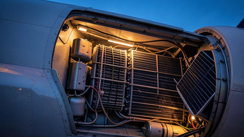
In a fuel cell, the waste heat appears inside the stack and has to be conducted into a coolant, pumped to a heat exchanger and transferred into air that must itself be moved through it. Every step carries hardware, mass, pumping power and drag. And the transfer is governed by the temperature difference available: a low-temperature stack in the sixty to ninety degree band is dumping heat into air that, on a hot day at sea level, may be within forty degrees of it. Small temperature difference means large area, and large area means a radiator that is an airframe object rather than a component.
A turbine expels waste heat through its exhaust, which also helps push the plane forward. A fuel cell needs extra systems to dump heat, which adds weight and drag. The bigger the engine, the more this difference matters.
On a hot day at a high-altitude airport, a fuel cell-powered regional jet might need a radiator the size of a small car to handle takeoff heat, while a turbine of the same power would just need a slightly larger exhaust nozzle.
| Hydrogen gas turbine | Fuel cell chain | |
|---|---|---|
| Where the loss appears | In the gas stream | In the stack, and again in the power electronics and the motor |
| Route out of the aircraft | Nozzle, with the working fluid | Coolant loop, heat exchanger, ram air |
| Temperature at which heat is rejected | Very high; the exhaust is far above ambient | Near stack temperature; a modest margin above ambient |
| Hardware this imposes | None beyond the exhaust that already exists | Radiators, ducts, pumps, coolant, and often two loops at different temperatures |
| Aerodynamic cost | Negative: the exhaust contributes thrust | Positive: cooling drag, partly recovered if the duct is designed to recover it |
| Behaviour as power grows | Absorbed by an exhaust that grows with the engine anyway | Grows in proportion, and the area must grow with it |
The last row eventually decides the argument. A turbine producing twice the power needs no separate system twice as large to reject its heat. A fuel cell chain does.
The radiator is sized by the worst moment, not by the cruise
The cruise point flatters the fuel cell: it is cold outside, ram air is abundant, and the stack runs at a current density where it is efficient and therefore not producing much heat. If cruise sized the cooling system, the fuel cell chain would look very attractive.
It does not. The sizing case is take-off, and more precisely the go-around: maximum power, low airspeed and therefore little ram air, high angle of attack, on the hottest day the certification basis requires and at the highest airfield elevation to be approved. Worse, maximum power is where the stack is least efficient — at high current density the cell voltage falls and the fraction of fuel energy becoming heat rises. The demand peak and the efficiency trough coincide.
So the heat exchanger is sized by a condition that lasts two minutes and occurs rarely, and that mass is carried for every hour of every flight. The mitigations are the familiar ones: hybridise with a battery so the stack need not meet the peak alone, absorb a short transient in the thermal inertia of the coolant, or design the aircraft so the peak is lower. Each buys relief and charges for it in mass somewhere else.
The trap. Comparing published efficiencies at the design cruise point and concluding that the fuel cell architecture is lighter. The cooling system is not sized at cruise, and the stack is not at its best at the point that sizes it.
What happens when you double the power
Scaling is where the two chains genuinely part company, and it is not a matter of technology maturity — it is geometry and thermodynamics.
A fuel cell stack is a repeating structure. Doubling the power means roughly doubling the active area. Mass doubles, heat doubles, the cathode compressor doubles. System specific power therefore stays broadly flat with scale: a bigger fuel cell is a bigger version of the same thing, with the same penalties per kilowatt.
A turbine does not behave that way. As size grows, tip clearances become a smaller fraction of blade height, Reynolds numbers rise, secondary flow losses fall proportionally, and the cooling technology and materials a small engine cannot justify become economic. Component efficiencies improve, achievable pressure ratios and turbine entry temperatures rise, and specific power improves with size. A bigger turbine is not a scaled version of a small one; it is a better one.
| Quantity | Fuel cell chain | Gas turbine |
|---|---|---|
| Mass | Grows close to proportionally with power | Grows less than proportionally; specific power improves |
| Efficiency | Broadly independent of size; set by the operating point on the curve | Improves with size, through component efficiency and cycle temperature |
| Heat to reject through hardware | Grows proportionally, and needs matching exchanger area | Very little: the exhaust carries the loss away, and only oil cooling scales |
| Auxiliaries | Compressor, pumps, humidification, filtration all scale with the stack | Accessory gearbox load grows slowly relative to core power |
| Volume in the airframe | Distributed: stacks, radiators, ducts, cabling, converters | Concentrated in a nacelle already accounted for |
| Part-load behaviour | Efficiency improves as power is reduced, until parasitic loads dominate near idle | Efficiency falls away from the design point |
Two curves, one flat and one rising, cross. That crossing is the boundary the question is asking about, and it exists whatever the state of the art — technology moves where it falls, not whether it exists.
Altitude changes the arithmetic twice
Climb to a typical jet cruise level and two things happen to a fuel cell chain, and they pull in opposite directions.
The favourable one is temperature. Ambient air in the mid flight levels sits around fifty degrees below zero in standard conditions, a very large difference for a stack running near seventy. On temperature difference alone, heat rejection at altitude looks easy.
The unfavourable one is density. At those levels the air is at roughly a quarter of sea-level pressure and less than a third of sea-level density, and the exchanger has to pass a mass flow. Losing two thirds of the density means much more area, much more velocity — which costs drag and pressure loss — or a smaller rejection capability. The temperature gain is real, but it is fighting a density loss.
Density hurts a second time, on the cathode side. The stack needs oxygen at a useful partial pressure, so the incoming air must be compressed, and the pressure ratio required grows with altitude. That compressor is driven by the stack’s own output, so the parasitic fraction climbs precisely as the air thins. This is one reason fuel cell concepts are proposed for aircraft that cruise lower and slower than a transport jet.
Part load, and the shape of the mission
The two chains have opposite part-load characters, and this is frequently the decisive argument for a specific aircraft rather than for a class of aircraft.
Reduce a fuel cell’s output and its efficiency improves over most of the range: lower current density means a higher cell voltage. Only near idle, where compressor and pumps take a growing share, does the trend reverse. Reduce a turbine’s output and efficiency deteriorates, sometimes sharply, as the cycle moves away from its design point.
Now put a mission profile against that. A regional operation on short sectors spends much of its energy in climb, descent, holding and ground operations — a great deal of time away from maximum power. A long-range operation spends almost all of its energy at a steady cruise, exactly where a turbine is optimised and where its part-load weakness never appears. That is why the boundary is not a number but a surface, with power on one axis and mission shape on the other.
What the fuel itself imposes on each chain
Hydrogen is common to both, and so is the tank, so storage is not what separates them. The storage facts are worth stating once because they set the context for either choice: per kilogram, hydrogen carries roughly two and a half to three times the energy of kerosene; per unit of volume, even liquid at around twenty kelvin, about four times less. The aircraft gets lighter and much bulkier, and the tank becomes a cryogenic structure with insulation, boil-off management and its own mass fraction. Both architectures pay that bill in full.
What is not common is what each chain demands of the hydrogen once it leaves the tank.
| Aspect | Fuel cell chain | Hydrogen turbine |
|---|---|---|
| Purity | Very demanding; catalyst poisoning by carbon monoxide and sulphur compounds is cumulative | Tolerant; combustion is indifferent to trace contaminants at these levels |
| Use of the cryogenic cold | Genuinely useful: the cold fuel is a heat sink that offsets part of the cooling burden | Useful for cycle intercooling or recuperation, but less structurally necessary |
| Combustion behaviour | Not applicable; electrochemical | High flame speed and wide flammability limits create flashback and flame-holding challenges, addressed by dedicated injector concepts |
| Nitrogen oxides | None produced | Depends entirely on flame temperature and residence time; lean and finely distributed combustion concepts aim to control it |
| Carbon emissions | None at the aircraft | None at the aircraft, apart from any lubricant burnt |
| Water vapour | Produced, at low temperature, without soot nuclei | Produced at roughly two and a half times the mass per unit of energy compared with kerosene, in a hot exhaust |
| Materials | Membrane, catalyst and bipolar plate durability under cycling | Hydrogen compatibility of seals, fuel system components and hot section materials |
The cryogenic cold row matters because it moves the boundary. A fuel cell installation that uses the liquid hydrogen as a heat sink recovers part of what its cooling system costs, and proportionally more than a turbine would. How much it recovers depends on fuel flow, which depends on power — so the coupling shifts the crossover rather than removing it.
The water vapour row calls for caution rather than emphasis. The climate effect of contrails depends not only on the water emitted but on how many particles are available for ice to nucleate on, on humidity and on temperature. A soot-free exhaust plausibly produces contrails with a different lifetime, but this is an open research question, and anyone quoting a firm number in either direction is ahead of the evidence.
Where the boundary actually falls today
Put the pieces together and the answer emerges without a threshold value.
Below the crossing, the fuel cell wins because the turbine has not yet reached the size at which it becomes good. Small turbines are relatively inefficient, and the heat rejection penalty is small in absolute terms because the losses themselves are small. Add a mission with much part-load operation, a modest cruise altitude and a modest cruise speed, and the fuel cell is comfortable.
Above the crossing, the turbine wins for the reasons the table listed: better specific power, efficiency improving with size, no dedicated rejection hardware, no compounding electrical chain, and a mission dominated by the steady high power at which it is at its best. The heat a fuel cell of that rating would have to move through radiators stops being a propulsion problem and becomes an airframe one.
Where does that put current programmes? Announced fuel cell propulsion work clusters at the commuter and regional end, on aircraft with modest cruise altitudes; announced hydrogen turbine work sits above it, at ratings where an electrical chain of the same power would be unattractive on mass alone. That is an industry-wide vote on where the crossover sits today, and a step change in stack specific power or exchanger effectiveness would move the line upward.
The right reflex. Faced with a claim about hydrogen propulsion, ask three questions first: at which mission point is the efficiency quoted, is the cooling system included in the mass, and what design case sized it. Most disagreements between credible engineers are about those three, not about physics.
What is still missing before either flies commercially
Neither architecture is limited today by the argument above. Both are limited by certification basis and industrial reality.
There is no mature certification basis for either chain. Existing engine and installation codes were written around a combustion engine burning a liquid hydrocarbon; a cryogenic tank near a pressurised fuselage, a high-voltage network at altitude and an electrochemical power source all raise questions those codes do not answer. The route in use is special conditions issued case by case, and the details will differ between authorities for some time.
Then there is everything that is not the aircraft: liquid hydrogen supply at airports, refuelling and turnaround times, boil-off on a night stop, ground equipment certification, and the rescue and firefighting implications of a fuel with those flammability limits. Those constraints apply identically to both chains — a useful reminder that the fuel cell versus turbine question is not the one that will decide when hydrogen aircraft enter service.
Comparable trade-offs are argued out in detail on the FL330 forums.


Leave a Reply
You must be logged in to post a comment.