
In type rating training, « flaps lower the stall speed » goes down without difficulty. The next question trips people up: why does the same aircraft stall at a lower angle of attack with flaps out than clean, even though it is producing more lift? And why does the configuration first deploy something at the leading edge before touching the trailing edge? Both families of devices increase maximum lift, and therefore lower the stall speed. They do not achieve it at the same point on the curve, and that difference governs everything else: pitch attitude, gust margin, drag, sequencing, and sensitivity to contamination.
Slats and flaps both help the wing fly slower, but they do it differently. Flaps give more lift at the same angle, making the plane stall at a lower angle. Slats let the wing fly at a higher angle before stalling. Mixing them up can be dangerous because one doesn’t replace the other.
On an Airbus A320, with slats extended but flaps retracted (configuration 1), the stall speed is about 100 knots at 1.3g, but the angle of attack margin is much higher than clean. Adding flaps (configuration 1+F) drops the stall speed to 90 knots but reduces the angle-of-attack margin. In turbulence, the slats-only config gives more safety even if the speed is higher.
Two levers, two places on the same curve
Everything can be read on the lift coefficient curve as a function of angle of attack. A trailing-edge device shifts it upward and to the left: at a given geometric angle of attack the wing produces more lift, the maximum is higher, but it is reached at a lower angle of attack than clean. A leading-edge device barely touches the linear portion: it extends the curve to the right, up to a noticeably greater angle of attack, and it is this extension that produces the additional maximum lift.
The visible result is the same — a lower stall speed — but the resource spent is different. The trailing edge buys lift and pays for it in available angle of attack; the leading edge buys available angle of attack and gives almost nothing at low angle of attack. A wing made high-lift by the trailing edge alone therefore offers a high maximum lift within a narrowed angle-of-attack range.
What a trailing-edge device actually does
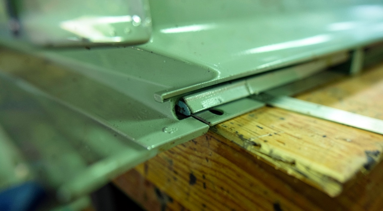
Three effects overlap, depending on the sophistication of the device. Camber: lowering the rear portion curves the mean line and increases circulation at constant angle of attack. Area: a Fowler-type flap translates aft and extends the chord; since the coefficients are referenced to the clean-wing reference area, this gain in real area appears in full in the coefficient. The slot: contrary to the popular image, it does not blow « high-energy » air over the flap’s upper surface. It organizes a multi-element aerofoil in which each element starts a fresh boundary layer instead of extending one that has already travelled the whole chord, and in which the pressure recovery demanded of each element becomes gentler than it would be on a continuous surface of the same camber. The detail of this mechanism, identical to the one that operates at the leading edge, is set out further on; it explains the single-, double-, or triple-slotted architectures, and the fact that two flaps deflected by the same angle do not render the same service if the slot geometry and overlap differ.
What remains is the drop in stall angle of attack, which always comes as a surprise. At a given angle of attack, the increased circulation from the flap strengthens the suction near the wing’s nose; the boundary layer starting there must climb a steeper gradient, and that gradient becomes critical at a lower geometric angle of attack than clean. The wing does not stall because the flap stalls: it stalls earlier at the front because the flap has increased its circulation. Separation begins where the trailing edge can do nothing about it.
Drag follows a law of diminishing returns: the last few degrees of a landing flap setting yield little lift and a lot of drag. That is not a flaw — it is what allows the glidepath to be flown at a thrust setting away from idle, hence with responsive engines, and produces firm deceleration on thrust reduction. The counterpart is mechanical: full configuration degrades the go-around gradient.
Pitching moment, for its part, cannot be inferred. Loading the rear of the aerofoil moves the centre of pressure aft and produces a nose-down moment on the wing; at the same time, the deflected wake alters the local angle of attack at the tailplane, whose sign depends on the tailplane’s position relative to that wake. The overall balance — hence the direction of the attitude change when flaps are extended — is type-specific: it is not derived by reasoning, it is read from the manual.
What a leading-edge device actually does: angle-of-attack range
The families differ in what they do with the slot. The movable slat translates forward and downward, opening a gap between itself and the main element. The leading-edge flap deployed from the lower surface acts mainly through the camber it adds to the nose, with or without a slot depending on its shape. The drooping leading edge pivots the leading edge downward. The fixed slot does not retract and therefore pays its drag permanently.
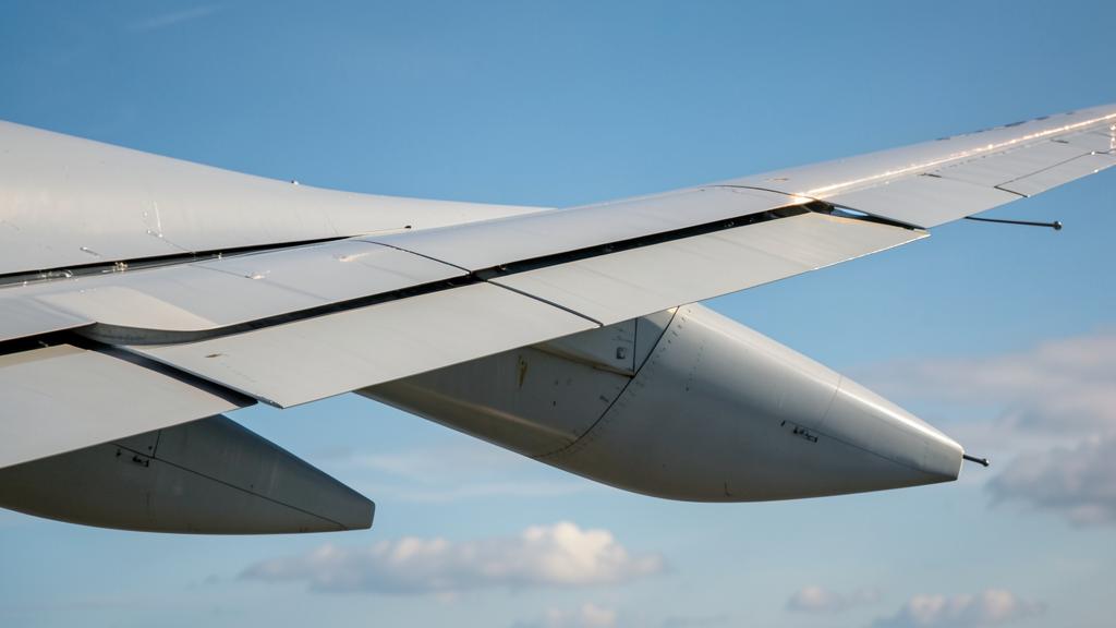
Leading-edge devices like slats work by creating a gap that helps air flow smoothly over the wing at higher angles. This lets the plane fly slower before stalling, giving pilots more margin in turbulence. But they cost extra drag when not needed, so they’re retracted at higher speeds.
The mechanism of a multi-element aerofoil breaks down into actions that, taken separately, add almost no lift at low angle of attack. The upstream element has its own circulation, which deflects the flow arriving at the main element’s nose and flattens the suction peak the latter would otherwise have had to bear alone. The trailing edge of the upstream element discharges into an accelerated flow, which eases its own pressure recovery. Each element restarts a fresh boundary layer, more resistant than a boundary layer that has already travelled the whole chord. And the wakes recover their pressure at a distance from the wall, where they cannot separate in the usual sense. The service rendered is not lift: it is deferring separation to higher angles of attack.
Two practical consequences follow. At cruise angle of attack, an extended slat contributes little and costs a great deal in drag, hence its retraction as soon as speed allows. And some types provide a position where only the slats are out, flaps retracted: this buys angle-of-attack range for manoeuvring or holding without paying the drag of a deflected flap. On several such types, the same lever detent adds a flap notch or not depending on the control logic, which makes reading the actual position a necessity.
Slot geometry is not an installation detail. Some devices provide a position where the slat stays flush against the aerofoil, slot closed, for take-off, and a deployed position for landing. The slot width and the overlap between elements account for most of the service rendered: this is what explains the strictness of rigging tolerances, and why a device that is extended but poorly rigged is not equivalent to one that is properly extended.
| Criterion | Leading-edge device | Trailing-edge device |
|---|---|---|
| Effect on the lift curve | Extends the curve toward higher angles of attack | Shifts the curve upward and to the left |
| Lift at ordinary flight angles of attack | Small gain | Immediate and significant gain |
| Angle of attack at maximum lift | Markedly increased | Reduced |
| Slope of the curve | Little changed | Slightly increased when area increases |
| Drag relative to the lift gained | Moderate, but penalizing at low angle of attack | Increasing, then dominant at large deflections |
| Attitude at approach speed | Little changed | Lowered: same lift at a lower pitch attitude |
| Angle-of-attack margin before a gust | Restored, and taken beyond the clean-wing value | Consumed |
| Effect on pitch | Loads the front of the chord | Loads the rear and alters the wake seen by the tailplane |
| Place in the sequence | First out, last in | Extended after the slat, retracted before it |
| Sensitivity to aerofoil contamination | Direct: ice attacks exactly what it produces | Indirect |
| Cost of a wrong position | Reduced angle-of-attack range, possible asymmetric stall | Degraded lift and climb gradient |
On a Boeing 737-800, with full flaps (config 40) at 135 knots, the angle-of-attack margin might be just 3-4 degrees. But in slats-only (config 1) at 150 knots, the margin could be 8-9 degrees. In strong turbulence, the higher speed with slats-only gives more safety because the angle-of-attack buffer is larger.
The margin that matters on approach is measured in degrees
A vertical gust does not change the aircraft’s speed: it changes its angle of attack. For a vertical component w and a true airspeed V, the change in angle of attack, expressed in radians, is approximately Δα ≈ w/V. A margin expressed in knots is therefore only a convenient translation; what the gust actually consumes is the gap in degrees between the flight angle of attack and the configuration’s maximum-lift angle of attack. Two configurations can offer the same margin in speed and very different margins in angle of attack.
Hence the unease felt flying a configuration heavily high-lifted by the trailing edge alone in turbulent air: the speed is comfortable, the angle is not. Hence also the fact that an escape manoeuvre in the face of windshear is flown by angle of attack, the only resource left when speed collapses faster than it can be rebuilt.
The right instinct — weigh a configuration in turbulent air in degrees before weighing it in knots: how much angle-of-attack range does this configuration leave available, and what remains of it once the attitude is already high to hold the glidepath? A speed increment compensates for a change in lift; it does not give back the angle of attack that rearward camber has taken up. This is what explains why a reduced flap setting prescribed by the type’s documentation should be read as restoring angular margin, not as giving up performance.
Why the order of extension and retraction is not up for discussion
On extension the leading edge comes first, on retraction the trailing edge goes first. This is not a manufacturer’s convention but the direct consequence of the geometry of the two curves. Retracting the slat before the flap brings the maximum-lift angle of attack back toward its clean value while the rearward camber still holds the aircraft at a high angle of attack: the margin vanishes at once, with no speed parameter to announce it. In the other direction, extending the flap before the slat raises circulation, hence the suction peak at the nose, before the device that flattens it has been installed.
Each notch is bounded by two speeds of a different nature: a maximum operating speed, a structural limit of the device and its mechanism, and a minimum manoeuvring speed, an aerodynamic limit specific to the configuration and generally a function of mass. Retraction after take-off proceeds as these milestones are passed, never ahead of them: a notch retracted too early is an amputation of available angle of attack at the precise moment when manoeuvring still occurs close to the ground.
Asymmetry deserves a separate mention, because its consequence is not merely a rolling moment. Since the leading edge fixes the local stall angle of attack, an asymmetric position means the less-equipped half-wing reaches its maximum lift before the other: the result is not a gradual imbalance but a roll-off as the limit is approached, precisely where the pilot has the least resource left. Hence the detection logic that freezes the mechanism as soon as a discrepancy is found, and the type procedures that impose a held speed and a fixed notch rather than a recovery attempt.
The protections are set for the configuration, not for today’s wing
The stall warning threshold, and on fly-by-wire aircraft the protection angles of attack, are programmed by table: to each pair of slat and flap positions, measured by sensors, corresponds a set of thresholds. The system does not measure the maximum lift actually available at that moment; it applies the value demonstrated for that configuration, on a clean wing, rigged within its tolerances, at deceleration rates defined by flight test.
Two failure paths follow from this, and they do not resemble each other. The first is instrumental: a faulty position sensor or a poorly rigged mechanism causes the thresholds of a different configuration than the one actually presented to the airflow to be applied. The second is aerodynamic: contamination of the aerofoil drops the actual maximum-lift angle of attack without anything moving the calculated threshold.
The trap — leading-edge contamination lowers the maximum-lift angle of attack without shifting the alert threshold, which remains that of the clean wing. The margin the warning is supposed to protect can then be zero: the alert arrives at an angle of attack the contaminated wing can no longer hold, and the stall manifests as a departure rather than a warning. The trap is all the more subtle because everything else appears normal — speed conforming, configuration as announced, threshold triggering where it always triggers.
The right instinct — as soon as leading-edge contamination is possible, stop treating the alert as a reference and read it as an indicator that has become optimistic. Apply the notch and speed additives prescribed by the type’s documentation for the contaminated wing, and manage the margin through speed and attitude rather than proximity to a threshold whose underlying assumption no longer holds.
Choosing a notch: a trade-off between the runway and the gradient
On take-off, a larger notch raises maximum lift, lowers the characteristic speeds and shortens the distances: the mass allowable under the runway-length criterion increases. But the additional drag degrades the gradient available after failure of the critical engine, and the mass allowable under the climb criterion decreases. The optimum is where the two limits cross, and it shifts with pressure altitude, temperature, surface condition, and the obstacle profile: the same runway does not call for the same notch from one day to the next.
On landing, a reduced notch raises the reference speed and lengthens the distance, but leaves a better gradient available on go-around and less drag. This is why some cases — icing, a device failure, strong wind or gusts — prescribe it explicitly. The price is paid elsewhere: more energy to dissipate at touchdown, hence more demand on the brakes and a tighter requirement on the touchdown point.
| Decision | What is gained | What is lost | Limitation that becomes dominant |
|---|---|---|---|
| Take-off, high notch | Lower speeds, shorter distances | Engine-out gradient, obstacle margin | Mass limited by climb |
| Take-off, reduced notch | Better gradient, better acceleration toward retraction | Longer distances, higher speeds | Mass limited by runway length |
| Landing, full configuration | Low reference speed, firm deceleration, lower attitude | Go-around gradient, angle-of-attack margin | Go-around performance |
| Landing, reduced notch | Go-around gradient, gust tolerance | Landing distance, energy to dissipate | Runway length and braking capacity |
| Slats only, flaps retracted | Angle-of-attack range for manoeuvring or holding | A little drag compared to clean | Fuel burn while holding, maximum operating speed |
On a short runway at high altitude (e.g., La Paz, Bolivia, 13,325 ft), an Airbus A320 might use full flaps (config 3) for takeoff to maximize lift and minimize distance. But if the runway is longer and obstacles are present, a reduced flap setting (config 2) might be used to maintain climb gradient after engine failure, even if it requires more runway.
On a swept wing, the leading edge also governs the order of the stall
On a swept wing, separation naturally tends to begin toward the outboard part of the wing, with two unfortunate consequences at once. The lost lift is located aft of the centre of gravity, which produces a nose-up moment that worsens the angle of attack at the very moment it should be reduced. And it is located exactly where the roll controls work, whose authority collapses just when it is most needed.
The sizing and rigging of leading-edge devices along the span form part of the answer, alongside vortex generators, fences, and devices that deliberately trigger early separation toward the wing root. The objective is not only to raise maximum lift: it is to impose an order on separation, from inboard to outboard, so that the stall manifests as a controllable sink rather than a departure. An undeployed or poorly rigged leading-edge panel should not therefore be read as a simple lift deficit: it changes the progression of separation, and hence the flying qualities demonstrated for that configuration.
What is left to check in the type’s documentation
With the mechanism now clear, the essential remaining work is to check it against what the operated type actually states, because architectures differ more than one might think. A few points deserve a careful reading rather than reliance on memory.
- The position table: which pair of leading-edge and trailing-edge positions each lever detent actually corresponds to, and which ones extend the slat without a flap.
- Where the minimum manoeuvring speeds by configuration are written, whether they vary with mass, and what they become in a turn.
- What the documentation prescribes exactly in the presence of icing: which notch, which speed additives, which alert reference remains valid.
- Whether the type has a load-relief function that retracts a notch beyond a given speed, and what it then does to the minimum manoeuvring speed.
- The asymmetry or jam procedure: speed to hold, notch to freeze, associated landing distances.
- What the minimum equipment list permits on a position sensor, and at what performance penalty.
A grey area remains, and it is more honest to name it than to paper over it. The characteristic speeds applied inherit from a demonstration performed on a clean wing, rigged within its tolerances, at a defined deceleration rate; the gap between that demonstrated wing and today’s wing — wear, repairs, light contamination, rigging at the edge of tolerance — is not covered by any figure in the flight manual, but by the additives, the procedures, and the margin the operator chooses to keep.
For anyone preparing a type rating, the shift to make is of the same kind: the useful question is not what flaps are for, but what changes if the slat is retracted before the flap, and why that particular action cannot be made up for with speed. The FL330 training courses address this trade-off configuration by configuration, and the edge cases are usefully discussed on the FL330 professional forums.
The applicable text, the type’s approved flight manual, and the operating documentation prevail in all circumstances over this article, whose purpose is to explain an aerodynamic mechanism, not to serve as a procedure or a limitation.
Questions fréquentes
Why does the stall speed go down while the stall angle of attack also goes down, flaps extended?
The two quantities do not measure the same thing. Stall speed depends on the maximum lift available, which the flap increases by adding camber and sometimes area. The angle of attack at which that maximum is reached nonetheless decreases, because the increased circulation strengthens the suction at the wing’s nose and makes the pressure gradient critical at a lower geometric angle of attack. You gain in speed while losing in angle-of-attack range.
Can the slats be retracted before the flaps if the speed is comfortable?
No, and speed is not the right criterion. Retracting the leading edge brings the maximum-lift angle of attack back toward its clean-configuration value, while the still-deflected flap keeps the aircraft at a high angle of attack: the angle-of-attack margin vanishes instantly with no speed parameter to announce it. The sequencing written into the type’s documentation reflects this geometry and admits no exception based on circumstance.
Why do some types provide a position with only the slats extended?
Because the leading edge provides angle-of-attack range without the extra drag a deflected flap brings. This position therefore offers a comfortable manoeuvring margin while holding, turning, or during a preparatory speed reduction, at a moderate energy cost. It is, however, useless in cruise, where the flight angle of attack is low and the device would only cost drag.
Is a reduced landing notch safer than a full configuration?
It shifts the risk rather than removing it. The reduced notch improves the gradient available on go-around and reduces drag, which explains its prescription in icing, on a device failure, or in strong wind. It does, however, raise the reference speed, lengthen the landing distance, and increase the energy to dissipate under braking. The choice is settled on the day’s performance data, not on a general preference.
Why can the stall warning arrive too late on a contaminated wing?
The alert threshold is programmed by table, based on the measured configuration, and it reflects a maximum lift demonstrated on a clean, correctly rigged wing. Leading-edge contamination lowers the actual maximum-lift angle of attack, but does not shift that threshold. The margin the alert is supposed to protect can then be sharply reduced, and the stall can manifest as a departure rather than a usable warning.
How does the take-off notch arbitrate between runway-limited mass and climb-limited mass?
A larger notch raises maximum lift, lowers the characteristic speeds, and shortens the distances, which raises the mass allowable under the runway-length criterion. The additional drag, however, degrades the gradient after failure of the critical engine, which lowers the mass allowable under the climb criterion. The mass retained is the lower of the two, and the optimal notch is the one that brings them closest together under the day’s conditions.


Leave a Reply
You must be logged in to post a comment.