
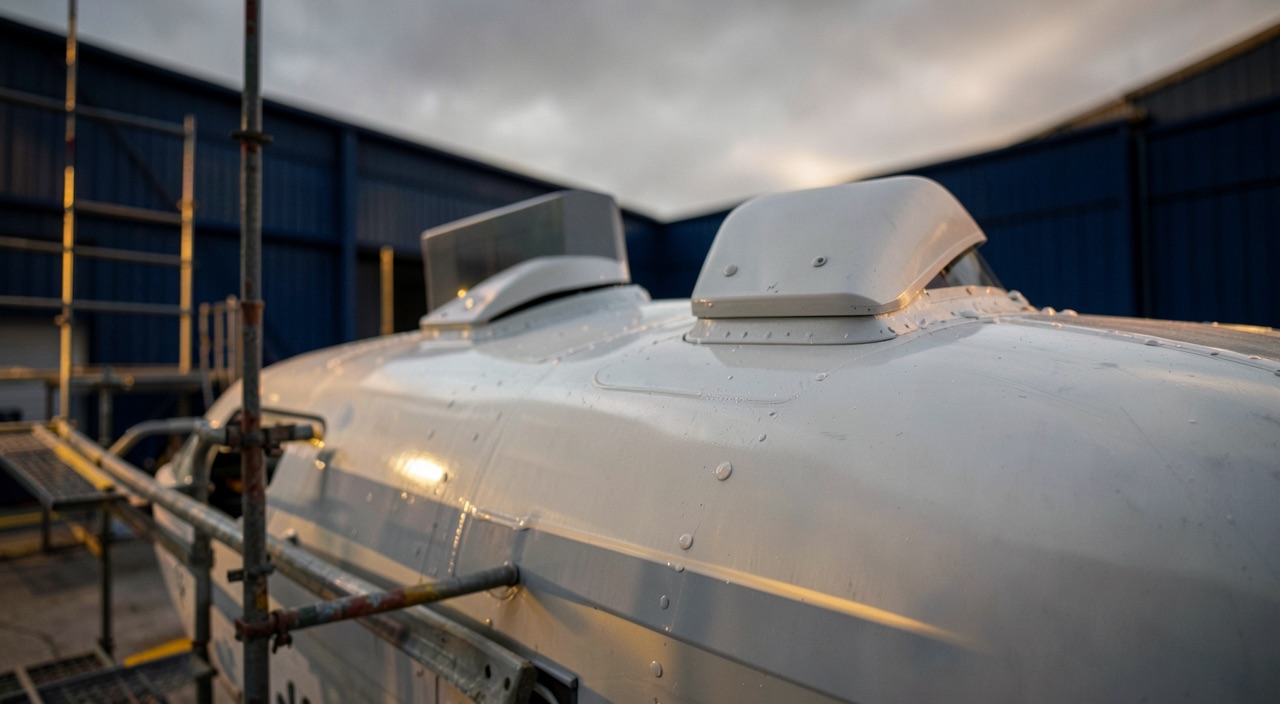
The aircraft comes out of the shop with one more antenna on its back. The two installations it now carries are each covered by a proper approval, each fitted according to its own instructions, each recorded in the file. Nobody has produced a single page examining the two together, and yet no signature is missing. The system approves changes one at a time, against a reference aircraft that the real aircraft stopped being the moment the first change was embodied — and the second file has no natural reason to notice.
An Approval Covers a Configuration, Not an Aircraft
A Supplemental Type Certificate, like any major-change approval, is processed against a certification basis and a defined scope. The applicant identifies the physical areas and functions affected by the change, then demonstrates compliance for that scope. Everything else remains covered by the original demonstration, the one made by the type certificate holder. It is this economy that makes the system workable: without it, the smallest equipment installation would reopen the certification of the entire aircraft.
The price of this economy is an implicit assumption, almost never spelled out in a file: outside the declared scope, the aircraft conforms to its type design. The resulting approval is then expressed as an eligibility list — models, series, sometimes ranges of serial numbers. It says nothing about the history of the specific airframe on which the change will be fitted, and it cannot: it is issued beforehand, and for a fleet.
Two independent approvals therefore cover three configurations out of four. The production aircraft is covered by the type certificate. The aircraft carrying the first change is covered by the first approval. The aircraft carrying the second is covered by the second. The fourth configuration — the one that actually flies — has been demonstrated by nobody, and nothing in either file flags this gap, since it is the oversight of neither.
When two changes are approved separately, the system assumes each works fine on its own. But when both are installed together, nobody checks if they actually work well together. The fourth configuration—the real aircraft—is flying without full approval.
A Boeing 737-800 receives a new satellite antenna (Change A) and a new in-flight entertainment system (Change B). Both are approved separately. Change A adds 50 amps to the electrical load, and Change B adds 30 amps. Individually, each stays within the 100-amp margin. But together, they exceed the 80-amp limit in a degraded power configuration, causing a system failure during a flight.
The authorities are not unaware of this, and certification specifications as well as guidance material expect the applicant to establish the configuration onto which his change is installed, then to address earlier changes affecting the same zones or the same functions. Yet this expectation is triggered by knowledge: one must know that the other change exists, and know what it does. The first point falls under the airframe’s configuration status, kept by the operator; the second, under design data belonging to a third party, which no general rule requires to be made available to others.
Where Two Independent Changes Meet
An interaction does not require physical proximity. Two pieces of equipment installed at opposite ends of the fuselage interact as soon as they draw on the same bus bar, share a data bus, occupy the same attention surface in the cockpit, or prescribe irreconcilable work in the same zone. The reflex of looking at the installation drawing to conclude there is no interference addresses only one of these channels, and not the most frequent one.
| Domain | What each file demonstrates on its own | What coexistence can produce |
|---|---|---|
| Electrical power | The added consumption stays within the margin of the reference load analysis | Two legitimate draws on the same margin, and an overrun in a degraded power configuration |
| Routing and segregation | The harness complies with separation rules with respect to the original harnesses | Two new harnesses routed side by side, with no separation rule addressing one against the other |
| Radio-frequency environment | The equipment meets the prescribed environmental levels and does not alter existing functions | Coupling between two new pieces of equipment, or antenna shadowing that neither drawing reveals |
| Structure and loads | The local reinforcement and fatigue strength are demonstrated on the production structure | Two cutouts or two attachment fittings added within the same bay, with the load path altered twice |
| Weight and balance | The mass and moment variation remains acceptable on the weighed airframe | A cumulative shift that pushes the empty-weight centre of gravity toward a limit, or that consumes the loading margin |
| Flight deck | The added controls, markings and messages are accessible and legible | Two additions competing for the same surface, the same control, or the same flight phase |
| Airworthiness documentation | An Aircraft Flight Manual supplement and a set of Instructions for Continued Airworthiness consistent with the existing documentation | Limitations that must be satisfied together, and tasks prescribed in the same zone at different intervals |
The middle column is the most instructive. Each file reasons in terms of available margin, and each measures that margin on the reference aircraft. Two regular draws on the same margin produce an overrun that neither analysis can see, because each is correct within its own frame. This is the generic mechanism of the unassessed interaction: there is no error to find in the files, only an addition that nobody was tasked with performing.
The Exact Moment the Analysis Disappears
The second change is fitted almost always by a maintenance organisation, from approved installation instructions. The mechanic checks eligibility: the model and series appear on the list, the aircraft is eligible. He opens the zone, records its condition, applies the file step by step, inspects, then issues the certificate of release to service. Each of these actions is correct and traceable. None of them includes an interaction review, and none of them should.
The reason is structural, not human: assessing the coexistence of two design definitions is a design act. A maintenance organisation has neither the privilege, nor the data, nor the means of demonstration to do so. It works on approved data; it does not produce it. Asking it for the analysis amounts to asking it to approve a change, which is exactly what the separation of approvals forbids it from doing.
Add to this the time gap. The two installations are rarely contemporaneous: often several years separate them, with a change of workshop, of state of registry, sometimes of owner in between. The only thing linking the two events is the airframe’s configuration status, that is, the list of embodied changes kept for continuing airworthiness purposes. When that list is merely a stack of references, with no indication of the zones and functions affected, it records history without allowing it to be interrogated.
Finally comes revision. An approval is alive: its holder amends it, broadens its eligibility, corrects an instruction, replaces a component that has become unobtainable. A compatibility examined once holds only for the design definitions in force on the day it was examined. Nothing automatically reopens the review when one of the two changes evolves, and the new revision settles in as a routine update.
The trap. The no-objection statement obtained from the first holder is taken as coverage. It is not: its author does not have the design definition of the second change, and therefore rules only on what he knows — his own product. Filed away, it creates the appearance of an interaction review where none took place, and it closes the question for every subsequent party.
Three Cumulative Effects Invisible at Installation
The electrical load analysis is the textbook case. Each file establishes the added consumption and compares it to available capacity, in normal operation and then in the degraded power configurations that actually size the margin. Both analyses are correct; they simply start from the same baseline, which is no longer the real starting point for the second. The overrun, when it appears, does not show up on the ground: it waits for the loss of a source and a load-shedding scheme that did not anticipate these consumers.
The weight-and-balance cumulative effect is even more discreet, because it is correctly recorded each time. Each installation triggers an update of the weighing report and the equipment list; the empty-weight centre of gravity shifts one notch, then another. Neither update is at fault. What is lost is the loading margin: the airframe ends up refusing loadings that its sister aircraft still accept, and the crew discovers it at loading time, not in the file.
The third cumulative effect is documentary. An aircraft flies under the combination of its flight manual and all its supplements: limitations add up, they do not replace one another. Two supplements can, over a narrow domain, require configurations that cannot both be satisfied. The same effect applies to the instructions for continued airworthiness, with two tasks prescribed in the same zone at different intervals, and to the minimum equipment list items, when the redundancy one supplement assumes to be available is precisely the one the other consumes.
The right reflex. Before starting the installation of a change, pull the configuration status of the specific airframe, not that of the model, and check the list of already-embodied changes against the zones and functions the new file declares as affected. A single intersection is enough to require a design opinion, and the time to ask for it is before the aircraft is opened up.
Who Must Produce the Analysis, and With What Data
The burden falls first on the applicant for the second change: it is he who declares the affected scope, and it is up to him to establish on which configuration his change is being installed. If he is targeting a fleet where earlier changes are widespread, he must either fold them into his demonstration or restrict his eligibility explicitly, in writing. An eligibility silent on this point is not a broad eligibility: it is an eligibility that never asked the question.
The obstacle comes next, and it is industrial in nature. The holder of the first change is, as a general rule, under no obligation to hand his design definition to a competitor. The second applicant therefore has only two ways out: obtain the agreement and the data of the first, or demonstrate compliance himself over the whole of the shared zone and functions, without relying on the first party’s work — which means taking on, at his own expense, part of what the other has already paid for. It is easy to understand why the third way out, the one that consists of never raising the subject, is popular.
There remains the operator, who processes nothing but holds the two pieces that make the question possible: the airframe’s configuration status and the purchase order for the job. He is the one who can require, before installation, that the supplier of the second change state in writing his position on the changes already embodied, and refuse a generic answer. The airworthiness review, for its part, checks that each embodied change is approved; « each one is approved » has never meant « the combination is approved. »
Regularising a Combination That Is Already Flying
The discovery rarely comes from an incident. It comes from a request for a new change that pokes into the zone, from a registration transfer where the receiving authority examines the design file line by line, or from an audit that traces a flight manual supplement back to its origin. By this stage, the aircraft has been flying for years, and the question is no longer whether the analysis should have been done, but which path can replace it.
| Path | What it covers | What it leaves open |
|---|---|---|
| Extension of the second change’s approval to the actually installed configuration | The combination becomes an approved case, with its own eligibility, documentation and instructions | Nothing, provided the declared scope encompasses the shared zones and functions: this is the only path that closes the subject |
| Separate design approval covering the combination | The shared zones and functions, examined by an organisation that has both definitions or redoes the demonstration | Future evolutions of either change, which reopen the review without warning |
| No-objection statement from the first holder | An opinion on the known effects of his own change, useful as an entry document | Any analysis of what the other change does, for which he has no data; this is not a design approval |
| Removal of one of the two changes | A return to a demonstrated configuration, if the removal itself relies on approved data | Residual effects of the removed installation: holes, fittings, wiring and mass left in place |
Only one of these paths produces a configuration that is approved and documented going forward. The others differ mainly in what they leave open, and the riskiest is the one that costs the least: a letter filed away closes the discussion without demonstrating anything, and the next generation of participants will read it as coverage.
What to Go and Look for in One’s Own File
Three checks give an honest picture without mobilising a design office. Take the configuration status of a given airframe and group the changes by affected resource — electrical generation, flight deck, same structural bay, same inspection zone: as soon as two references fall into the same group, the intersection is worked out by hand instead of being assumed absent. Then pull out all the embodied flight manual supplements and read them straight through, the way a crew should be able to, looking for limitations that cannot both be satisfied. Finally, check, on the last installation job, what was asked of the supplier about the changes already present, and what he answered.

A grey area remains, one that nobody settles in writing: the threshold beyond which two changes « touch » each other. Two antennas spaced apart on the same skin appear unrelated, until one considers the radiation pattern, the ground return, or the structural bay that carries them. The practical criterion is not distance but shared resource — a bus bar, a data bus, a structural bay, an interval, a second of attention. Every shared resource is an interface, and every interface deserves a written sentence, even when that sentence concludes there is no effect.
For anyone preparing a certifying staff qualification or a role in continuing airworthiness management, the question almost always comes down to the same form: what do you check before installing an approved change on an aircraft that already carries others? The expected answer is not the eligibility list, it is the intersection of scopes and the name of whoever must examine it. Concrete cases are discussed on the FL330 forums, and preparation for airworthiness roles is covered on the training side.
This article describes a certification mechanism and does not replace any official source. The rules applicable in the State of Design and the State of Registry, the conditions written on each approval, the approved aircraft documentation, and the operator’s procedures all prevail over what is written here.
Questions fréquentes
Do two modifications located far apart on the aircraft still require an interaction review?
Yes, as soon as they share a resource, because distance only guards against part of the possible couplings. Two pieces of equipment located at opposite ends of the fuselage meet on electrical generation, on a data bus, on weight and balance, on crew attention, or on documentation. The useful criterion is therefore not the installation drawing but the list of shared resources, and a single intersection is enough to justify a design opinion.
Is a no-objection letter from the first holder enough to cover the combination?
No, because its author does not have the design definition of the second change and can only rule on his own product. Such a letter is useful as an entry document for a file, never as a compliance demonstration, and it does not constitute the approval of any configuration. Only a design approval explicitly covering the actually installed configuration closes the subject.
Can the maintenance organisation fitting the second modification refuse the job?
He can and must refuse if he finds that the aircraft is not in the configuration assumed by the installation instructions, for example because an earlier change occupies the opened zone. This refusal is not a design judgment: it simply notes that the approved data he has does not cover the aircraft in front of him. What happens next is for the supplier’s design office or an approved design organisation to decide.
What should be done when the situation is discovered on an aircraft already in service?
The first step is to characterise the actual intersection: which zones and functions do the two approvals declare as affected, and where do they overlap. Depending on the outcome, one asks the holder of the second change to extend his approval to the installed configuration, has a design approval covering the combination processed, or removes one of the two. An immediate risk assessment must accompany this process, since it takes time and the aircraft keeps flying in the meantime.
Does the airworthiness review detect this type of gap?
It detects it poorly, because it checks that each embodied change is covered by a valid approval and that its documentation is present. This check is satisfied even though the combination has never been assessed. A useful review requires adding a cross-reading of the declared scopes, which is more a matter of initiative by the continuing airworthiness management organisation than an explicit requirement of the check itself.


Leave a Reply
You must be logged in to post a comment.