

Minus thirty on the ground, an RNP APCH with an LNAV/VNAV line and, beneath the minima box, a note prohibiting baro-VNAV below a certain temperature. The display, for its part, says nothing: vertical deviation centred, displayed angle consistent with the chart, stable descent. That is exactly the problem: the aircraft is following, without error, a path that on this particular day settles beneath the one the designer protected — by a margin that runs to hundreds of feet upstream of the threshold.
What the altimeter measures, and what baro-VNAV does with it
A barometric altimeter does not measure altitude: it measures static pressure and converts it into height by means of a fixed law, that of the standard atmosphere. The QNH setting only shifts the origin of that conversion: it places the zero of the scale at sea level as the station derives it from its own pressure, and it is rigorously accurate only in the vicinity of that station. The conversion law itself remains that of the standard atmosphere, whatever the column of air actually traversed.
Baro-VNAV inherits this convention in full. The computer reconstructs a geometric path — an angle anchored on the threshold and on a reference crossing height — then expresses it in barometric altitudes and flies the aircraft to null the deviation. The vertical deviation displayed to the crew is therefore a difference between two barometric altitudes: it says nothing about the actual height above the ground, and it is that actual height which determines the obstacle margin.
Satellite-based vertical guidance, by contrast, works from a geometric height derived from GNSS, indifferent to the temperature of the air column. In extreme cold, two successive aircraft — one on baro-VNAV, the other on satellite guidance — do not fly the same physical path.
Cold compresses the column, and the slope sags
In cold air, density is higher: pressure decreases more rapidly with altitude, and the isobaric surfaces bunch together closer to the ground. A given pressure is therefore physically encountered lower than the standard atmosphere predicts. The altimeter, applying the standard law without knowing any better, assigns that pressure too high an altitude: it over-reads. True altitude is lower than indicated.
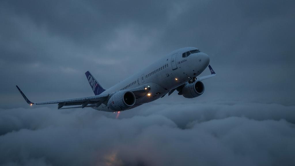
The decisive point is not the existence of this error, but its distribution: it is zero at the level of the pressure-setting source and grows with height above that source, in roughly proportional fashion. Now, height above the aerodrome is small near the threshold and large at the final approach fix. The error is small at the bottom, large at the top.
In cold air, the altimeter over-reads because pressure drops faster with altitude. This means the aircraft is actually flying lower than the altimeter says. The flight path angle looks correct on the display, but in reality, the plane is descending too shallowly, risking hitting obstacles.
An Airbus A320 on baro-VNAV at an airport with a 3,000-foot runway elevation and -30°C temperature. The final approach fix is at 3,500 feet indicated altitude. The actual altitude is 3,240 feet (3,500 – 240 feet over-read). The path angle appears correct, but the plane is 240 feet lower than planned, risking terrain clearance issues.
Why the discrepancy grows further upstream
The path actually flown links a point barely lowered, near the threshold, to a point strongly lowered, at the final approach fix: its vertical drop is smaller than that of the published path, while its horizontal length is unchanged. The actual angle is therefore smaller than the displayed angle, and the entire flight path lies below the nominal path, with a discrepancy that grows further upstream. Each intermediate step-down is crossed lower than planned, and the one indicator that could warn of it — the vertical deviation — is, by design, centred.
The reasoning reverses term for term in warm conditions: expanded column, altimeter under-reading, true altitude higher than indicated, actual angle steeper than the coded angle, trajectory above the published path. The obstacle margin improves, but the gradient actually flown increases, which weighs on stabilisation and on maximum-altitude constraints.
Two thermal regimes, one rule for reading them
Everything hinges on the order of reasoning: air density, direction of the error, true altitude, then the angle and the margin.
| Quantity | Air colder than the standard atmosphere | Air warmer than the standard atmosphere |
|---|---|---|
| Air column | Dense, isobars bunched toward the ground | Expanded, isobars spread apart |
| Altimeter behaviour | Over-reads | Under-reads |
| True altitude vs. indicated | Lower | Higher |
| Distribution of the error | Zero at the station, increasing with height | Zero at the station, increasing with height |
| Angle actually flown | Shallower than the coded angle | Steeper than the coded angle |
| Position of the flight path | Below the published path | Above the published path |
| Obstacle margin | Eroded | Increased |
| Dominant concern | Terrain clearance | Gradient, stabilisation, high-altitude constraints |
Orders of magnitude: the rule of thumb, and what it’s worth
The usual formulation puts the over-read at roughly four feet per thousand feet of height and per degree Celsius of deviation from the standard atmosphere. Two precautions account for most of the calculation errors made in the flight deck. The input variable is the deviation from the standard atmosphere, not the raw temperature: the aerodrome temperature is compared with the standard value at the elevation of that aerodrome. The second is the height above the pressure-setting source, not altitude above mean sea level; at a high-elevation aerodrome, confusing the two absurdly inflates the correction.
| Deviation from the standard atmosphere | 1,000 ft | 2,000 ft | 3,000 ft |
|---|---|---|---|
| −10 °C | ≈ 40 ft | ≈ 80 ft | ≈ 120 ft |
| −20 °C | ≈ 80 ft | ≈ 160 ft | ≈ 240 ft |
| −30 °C | ≈ 120 ft | ≈ 240 ft | ≈ 360 ft |
| −40 °C | ≈ 160 ft | ≈ 320 ft | ≈ 480 ft |
The approximation is linear, assumes a regular thermal lapse rate, and degrades for extreme deviations: it serves to convey the scale, not to make decisions. Nor does it say anything about the case where the cold layer is a thin inversion close to the ground, a situation in which the error builds up almost entirely within the first few hundred feet instead of growing steadily. The tables in the approved documentation, by contrast, are not approximations.
The trap. The low limit printed on the chart qualifies only the barometrically guided final segment. Reading it as ‘temperature above the limit, so nothing to do’ is a reasoning error: minimum altitudes for the initial and intermediate segments, minimum sector altitudes, level segments and the go-around remain the crew’s responsibility and require correction well before the published limit is even reached. An approach that is perfectly legal with respect to baro-VNAV can still be flown with uncorrected step-downs.
Why a low temperature limit appears on the chart
The obstacle clearance height of an LNAV/VNAV line is not obtained by stacking flat margins: it results from a vertical error budget aggregating altimetry, flight technical error, onboard system error, and coding uncertainties. That budget is established for a temperature range; below its lower bound, the lowering of the flight path exceeds what was allowed for, and the stated protection ceases to be guaranteed.
The low limit is therefore a design outcome, not a comfort margin. It applies to the reported temperature of the aerodrome, not to the air temperature at flight level, and it governs only barometric guidance down to the LNAV/VNAV decision altitude. A high bound is sometimes published for the symmetrical reason: to avoid an excessive actual flown gradient.
| Situation | Barometric vertical guidance | Minima line used | Corrections the crew must apply |
|---|---|---|---|
| Temperature within the published range | Usable | LNAV/VNAV decision altitude | Minimum altitudes outside the final segment |
| Below the low bound, without approved compensation | Not to be used for guidance | LNAV line minimum, corrected | All of them, including the final step-down and the go-around |
| Below the low bound, with compensation approved and authorised by the operator | Usable within the terms of the approval | As per the approval and the chart note | Whatever the compensation does not cover, established before the flight |
| Satellite vertical guidance available, aircraft approved | Not applicable | Satellite-guided line | Minimum altitudes outside the final segment |
Correcting an altitude is not correcting a slope
A manual correction adds an increment to a published minimum altitude, so that the true altitude actually reached again becomes the one the designer had in mind. It is valid for a point or a level segment: one value, one reference height.
A flight path, however, is defined by an angle, and an angle cannot be corrected with a constant. Raising the final-approach-fix crossing altitude and then following the coded angle leads above the reference crossing height; following the path computed by the system cancels the correction within seconds, since that path is built in the uncorrected barometric reference frame. The two actions are incompatible: below the low bound, the answer is not ‘correct, then keep the vertical guidance’, but ‘abandon barometric guidance’.
What the correction changes not at all
- All aircraft set to the same reference are subject to the error in the same direction: vertical separation is therefore not called into question by the cold.
- If anything, since the error grows with height, the true gap between two stacked levels is very slightly compressed relative to the indicated gap — a marginal effect at the separation values used, and nowhere near comparable to what genuinely deteriorates, namely the margin above the ground.
- Hence a rule of conduct that admits no exception: correcting an altitude assigned by ATC on one’s own initiative changes the level actually occupied and must be reported to ATC.
The right reflex. Decide before the initial approach fix, not on final. At the briefing: aerodrome temperature compared with the low bound, minima line selected and briefed, correction increment already computed for the relevant step-downs and for the go-around, and — if a compensation is active — an explicit statement that the displayed altitudes will be higher than those on the chart. A crew that discovers the temperature note while selecting the approach no longer has time to recompute step-downs, renegotiate a minima line, and redo a briefing all in the same breath.
Onboard compensation: what is corrected, what is not
Some flight management systems have an approved temperature compensation function. When it is active, it raises the barometric path so that the geometric path actually flown coincides with the one intended by the design. The trade-off surprises anyone who hasn’t anticipated it: the computed altitudes, in particular that of the final approach fix, become higher than those on the chart. This is normal operation, not an anomaly.
Three questions are settled on the ground, in the operator’s documentation. Does the compensation apply only to the final path, or also to the altitude constraints of the rest of the procedure? Does it cover the decision altitude and the go-around? Is it automatic, or dependent on entering a temperature? Finally, the approval decides whether its use permits descending below the published bound: this is never automatic.
The second trap. A compensation fed by a manually entered value becomes wrong as soon as that value is stale: a temperature entered for a contemplated diversion, then forgotten, produces a path corrected for an aerodrome other than the one being descended into — and the display flags nothing. Symmetrically, a crew that mistakes the discrepancy between the computed final-approach-fix altitude and the chart altitude for a database error may disable a legitimate compensation at the worst possible moment.
The cross-checks that actually see the geometry
No barometric instrument can detect the phenomenon: they all share the same convention. Two geometric references remain.
The radio altimeter measures a true height above the terrain overflown: a systematic discrepancy between its value and the expected height on final is the physical signature of the phenomenon. It is not a guidance source — the terrain is not flat — but it is a useful briefing item where the approach terrain profile is known and regular.
The visual approach slope indicator, on the other hand, defines an optical plane in real space: it is by nature insensitive to temperature. On a baro-VNAV approach in extreme cold, finding oneself low on the visual indicator while the vertical deviation is centred is not a contradiction — it is the expected consequence of the mechanism. Knowing the sign of this discrepancy in advance avoids hesitation at the visual transition.
Two elementary checks remain, and they are often the only ones missing: a local, current QNH — baro-VNAV must not be flown on a remote setting, whose error is not included in the design budget — and, before the final approach fix, a comparison between the computed values and those on the chart.
What to go and check in your own documentation
A few points remain to be established before they are needed. Is the compensation approved on the relevant fleet, and is its scope written into the operations manual? Is the operator’s policy on correcting an assigned altitude formally stated, or is it a matter of local custom? Is the correction table used the one from the approved documentation, and is its reference-height convention understood the same way by both pilots? Is the fallback to the LNAV line with a corrected minimum practised, or merely mentioned?
Two grey areas remain. Handling of the intermediate segment and of the go-around in cold conditions varies in its degree of formalisation from one operator to another, even though that is exactly where the margin is decided when the low bound is respected. And the case of an aerodrome where the bound is respected but where the intermediate minimum altitude becomes the sizing constraint deserves explicit treatment. For anyone preparing a type rating or a module of performance-based navigation training, the exam question focuses on the direction of the error and the anchoring of the correction, never on the arithmetic.
This article sets out a mechanism and its usual operational handling; it does not constitute a procedure or an authorisation. In the event of any discrepancy, the applicable regulatory text, the current charts, and the operator’s approved documentation take precedence over what is written here.
Questions fréquentes
In cold weather, does the altimeter read too high or too low?
It reads too high. Since cold air is denser, pressure decreases more rapidly with altitude, and a given pressure is physically encountered lower than in the standard atmosphere; the altimeter, which applies that standard law, assigns it an altitude higher than the true altitude. The error is zero at the level of the pressure-setting source and grows with height above that source, which makes it small near the threshold and significant at the final approach fix.
Why is baro-VNAV prohibited below a certain temperature?
Because the obstacle clearance height of the LNAV/VNAV line was established with a vertical error budget valid for a specific temperature range. Below the lower bound of that range, the trajectory actually flown descends lower than the budget allowed for, and the stated protection ceases to be guaranteed. The limit is therefore a design outcome, not a comfort margin, and it applies to the reported aerodrome temperature.
Can you correct the final approach fix altitude and still follow the computer's vertical path?
No, the two actions are incompatible. A correction is an increment added to a single-point altitude, whereas a flight path is defined by an angle, which cannot be corrected with a constant. Following the computed path, built in the uncorrected barometric reference frame, cancels the correction within seconds. Below the low bound, the correct approach is to abandon barometric vertical guidance and fly the LNAV line with a corrected minimum.
Does cold weather degrade vertical separation between two aircraft?
No, not in any way that matters. All aircraft set to the same reference are subject to the error in the same direction and in similar proportions, so their true separation remains very close to their indicated separation; since the error grows with height, that true separation is even very slightly smaller than the displayed separation, which remains negligible at the separation values used. What genuinely deteriorates is the margin above the ground and obstacles. That is why a correction applied on one’s own initiative to an altitude assigned by ATC changes the level actually occupied and must be reported to ATC.
Is satellite-based vertical guidance affected by the temperature limitation?
No, because it builds its trajectory on a geometric height derived from GNSS, independent of the temperature of the air column. Some charts explicitly state that the limitation does not apply to aircraft using satellite vertical guidance down to the same decision altitude. What remains to be checked is the approval of the aircraft and the operator, as well as the note actually printed on the chart in use.
What exactly does a flight computer's temperature compensation function correct?
The scope is specific to each implementation and is found in the aircraft’s approved documentation as well as in the operations manual. Some functions only raise the final path; others also handle the procedure’s altitude constraints, the decision altitude, and the go-around altitudes. When the compensation is active, the computed altitudes become higher than those printed on the chart: this is normal operation, not a database error.


Leave a Reply
You must be logged in to post a comment.