
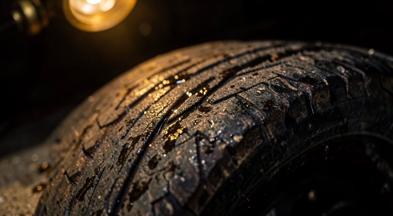
A main landing gear tyre comes back from a stopover with an oval patch of smooth, tacky rubber on part of the tread, and the runway carries white marks in the same spot where black marks would be expected. No report from the flight deck: the landing simply felt long. These two clues are enough to establish that a wheel stayed locked on a film of water brought to a boil, and that grip had vanished well before the sensation of deceleration signalled it. Everything played out inside the contact patch, on an area that inflation pressure alone is enough to calculate — and the three ways of losing contact in it share neither the same physics, nor the same speed range, nor the same remedy.
The contact patch does not carry an area, it carries a pressure
An aircraft tyre is not a rigid part but a flexible envelope held under pressure. The carcass takes part in carrying the load, but the vertical equilibrium is essentially provided by the gas: to a first approximation, the contact patch area equals the load carried by the wheel divided by the inflation pressure. The consequence is central and counter-intuitive. The pressure exerted on the pavement barely depends on the aircraft’s mass: it stays close to the inflation pressure. A more heavily loaded wheel does not press harder, it presses over a larger area.
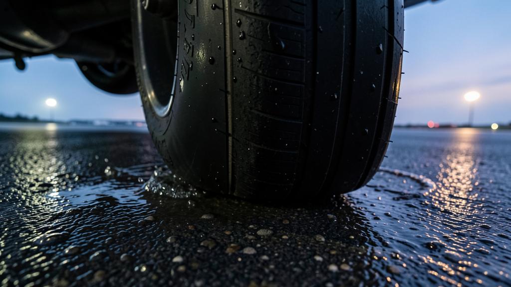
On a wet surface, this contact patch is not uniform. It splits into three zones found consistently from one test to the next. At the front, a displacement zone, where the mass of water is thrown sideways and forward and the rubber touches nothing. In the middle, a transition zone, where a thin film remains that the time of passage was not enough to expel. Only at the rear, a zone of true contact, where the rubber actually bears on the texture. It is this last zone, and this zone alone, that produces braking and steering.
The hydrodynamic pressure developed in the water wedge grows as the square of speed. The wedge therefore advances rearward as speed increases, the zone of true contact shrinks, and the available friction decreases continuously well before any total loss. Full hydroplaning occurs when the average hydrodynamic pressure balances the lift pressure of the contact patch, that is, the inflation pressure. The wheel then stops rolling on a solid and planes on a liquid, like a hull on its step. From this balance follows the one useful scaling rule: hydroplaning speed varies as the square root of inflation pressure. An old empirical relationship, drawn from tests on a smooth tyre in standing water, puts this speed in knots at roughly nine times the square root of the pressure expressed in pounds per square inch, and at roughly seven point seven times that root for a wheel that is not rotating. Three assumptions underlie it, all false in operations: smooth tread, water depth greater than groove depth, pavement with no useful texture. It therefore gives neither a limit nor a margin, only a dependency — and the square root says right away that a lot of pressure does not buy much speed.
The contact patch is the area where the tyre touches the ground. When wet, water gets trapped between the tyre and pavement, reducing grip. At high speeds, this water forms a wedge that pushes the tyre up, making it float like a boat. The more pressure in the tyre, the higher the speed needed for this to happen. But even with high pressure, too much water or worn tyres can cause hydroplaning at lower speeds.
On a Boeing 737 with 180 psi tyre pressure, the dynamic hydroplaning speed in 6mm of standing water is about 120 knots. If the tyres are worn down to 2mm tread depth, the same aircraft can hydroplane at just 80 knots in the same conditions. A 20% underinflation (144 psi) would lower this threshold to around 105 knots for new tyres, showing how small pressure changes have limited effect.
Three regimes, three physics, one word
Hydroplaning is spoken of in the singular, yet three distinct mechanisms hide behind the word. Confusing them leads to applying the remedy for one to the situation of another.
The dynamic regime is the one described in the preceding paragraph: it requires a real depth of water, appears above a speed threshold, and disappears once speed drops back below it. It is the only one of the three that clears on its own. The viscous regime needs almost no water: a film a few tenths of a millimetre thick is enough, provided the pavement is polished. It is the viscosity of the film, not its inertia, that prevents expulsion. It has no marked speed threshold, persists down to very low speeds, and occurs wherever microtexture has disappeared — hence in the touchdown zone loaded with rubber deposits, on painted markings, on aged, closed-up pavement.
The third regime assumes a wheel that is locked or nearly so. The rubber rubs without turning, the dissipated energy brings the trapped water to a boil, the pressurised vapour lifts the tyre, and rubber carried past its vulcanisation temperature reverts to a tacky state that finishes sealing the film. This regime is self-sustaining, does not yield with speed, and only stops when the brake is released to let the wheel resume rotation. It leaves two lasting signatures: the patch of reverted rubber on the tyre, and the white marks on the runway, the steam having scoured away deposits instead of adding to them.
| What distinguishes them | Dynamic regime | Viscous regime | Reverted rubber |
|---|---|---|---|
| Mechanism | Hydrodynamic pressure of the water wedge | Thin film held by its viscosity | Pressurised vapour and devulcanised rubber |
| Water required | Depth greater than groove volume | A few tenths of a millimetre | A film is enough, it gets trapped then vaporised |
| Speed range | Above a threshold linked to inflation pressure | No marked threshold, persists very low | Indifferent, self-sustaining down to a stop |
| State of the wheel | It slows, then stops turning | Partial slip, rotation retained | Locked or nearly locked, by construction |
| Effect of inflation pressure | Direct, as a square root | Weak | Indirect, through retained rotation |
| Effect of the pavement | Macrotexture and drainage | Microtexture and rubber deposits | Second order |
| Available cue | Spray plume, absent deceleration, wheel speed | Mediocre braking with no sharp break | White marks and oval patch, after the flight |
| What stops it | Decreasing speed | A texture that breaks through the film | Releasing the brake, nothing else |
Inflation pressure and wear: the two levers on the tyre’s side
Since the threshold follows the square root of pressure, a few percent of underinflation shifts almost nothing; a substantial underinflation, on the other hand, clearly lowers the threshold and does so in less water. The mechanism is twofold: the contact patch enlarges, so its lift pressure drops and the water wedge gains ground faster; and the increased sidewall flexing heats the structure, which raises the pressure and partly masks the defect at the next check.
Hence the requirement for a cold check, aircraft stationary long enough for the heat from taxiing and braking to have dissipated. The gas law is enough to quantify the illusion: around ambient temperature, a change of roughly three degrees shifts the pressure by about one percent. A check made right after taxiing, or near a brake still hot, gives a flattering value. Nitrogen, retained as the inflation gas on types whose brakes run hot, changes nothing about this physics: it removes the oxidiser, hence the risk of pyrolysis gases igniting in an overheated wheel.
On a dual-wheel bogie, a pressure difference between two paired wheels is not compensated. The better-inflated wheel is stiffer, deflects less and takes on an extra share of the load; its neighbour, less loaded but more deflected, works on a contact patch whose lift pressure is lower, and it is this wheel that hydroplanes first. Asymmetric hydroplaning on the same landing gear is not visible, but it produces a yawing moment and a differential deceleration that the anti-skid system can only observe.
The trap. A wheel that loses its pressure is not an isolated event: its twin has absorbed the load of both, often outside its rating, and its tyre structure as well as its bearing may have been compromised with no outward mark. Replacing the failed wheel while leaving its neighbour in service because it looks intact is a classic mistake; the type’s maintenance manual most often prescribes the opposite, and it is that document which sets the procedure.
The right reflex. Log the pressure together with the temperature and the time since the last taxi run, never the pressure alone. A bare figure cannot be interpreted. It is the slow drift between two comparable checks — same conditions, same time of day — that reveals an abnormal leak, well before any single check falls outside tolerance.
Wear acts elsewhere. Grooves do not create grip: they give water a volume to escape into and a path out of the contact patch. That volume shrinks with remaining depth, and with it the depth of water the tyre tolerates before the dynamic regime sets in. A tyre near the end of its life therefore does not hydroplane at a very different speed from a new tyre in deep water — the threshold depends on pressure alone — but it hydroplanes in a much thinner sheet of water, hence much more often. And wear is rarely uniform: a centre rib worn down by chronic overinflation, or shoulders worn by the opposite, remove drainage exactly where the contact patch works hardest.
| Parameter | Effect on the threshold | Mechanism | Who controls it |
|---|---|---|---|
| Inflation pressure | Raises it, as a square root | The lift pressure of the contact patch balances the hydrodynamic pressure later | Maintenance |
| Tyre temperature | Raises it slightly | Pressure rise from the gas law, with no exploitable margin | No one: cannot be credited |
| Tread depth | No effect in deep water, but lowers the critical water depth | The available drainage volume decreases with wear | Maintenance |
| Load on the wheel | Weak effect on the threshold | The contact patch grows, its pressure stays close to inflation pressure; the transmissible force, though, increases | Flight crew, through the destruction of lift |
| Runway grooving and macrotexture | Raises it | Residual water depth reduced under the contact patch | Aerodrome operator |
| Water depth | Lowers it up to saturation | Beyond groove volume, the tyre behaves as if it were smooth | Drainage and weather |
The pavement matters as much as the tyre
Two scales of roughness are at work, and they do not serve the same function. The macrotexture, the one you can see and feel with a hand, opens the escape paths: it reduces residual water depth and delays the dynamic regime. It is what transverse grooving, porous friction courses and the pavement’s cross-slope are aimed at. The microtexture, at grain scale, is what breaks through the thin film: it alone counters the viscous regime. A pavement can be excellent in one and poor in the other — grooved concrete polished at the surface sheds free water yet stays slippery under a film.
The operational consequence is unwelcome: the viscous regime develops preferentially in the touchdown zone, where rubber deposits have filled in the microtexture, and where speed is still high and the load on the wheels still low. Painted markings and repaired patches add islands of the same kind. Runway condition reports, finally, must be read for what they are. The condition code, on a seven-step scale running from the most slippery surface to a dry runway, describes the contaminant and the surface, not the behaviour of a given tyre, at its pressure and state of wear. The conventional three-millimetre threshold, which separates wet runway from standing water, is a contaminant-category threshold, not a hydroplaning threshold. Ground friction measurements taken by a vehicle do not transpose any better: lift pressure, speed and load bear no resemblance to those of a landing gear, and that is precisely why reporting has shifted toward a description of the condition rather than toward a coefficient value.
Why the loss is directional first
The same interface produces both braking force and steering force, and their vector sum is bounded by what the zone of true contact can transmit. This is the friction ellipse: what is drawn off for braking is no longer available to hold the axis, and vice versa. When a contact patch hydroplanes, the two are lost together, but not at the same perceived moment. The loss of braking is noticed immediately, because it is called on constantly; the loss of steering only shows up the instant a deviation must be corrected, which means once that deviation already exists.
The nose wheel is the most exposed and the least useful. It meets undisturbed water, it is the one that produces the spray plume, and its contact patch is small. Above all, the authority of nosewheel steering is proportional to the load it carries, low at the start of the roll and for as long as residual lift has not been destroyed. Turning a hydroplaning nose wheel produces nothing. There is then a crossover of authority worth keeping in mind: rudder authority is effective as long as speed is high and its effectiveness collapses as the square of speed, whereas the wheels only regain true contact once water has been expelled and load established, hence low. Between the two there remains a band where neither the aerodynamics nor ground contact provide clear authority — exactly the band where the viscous regime and reverted rubber persist, since neither has a low threshold.
The trap. Reverse thrust is tied to the fuselage, not to the flight path. As soon as an angle develops between the fuselage axis and the track over the ground — residual drift, crosswind, asymmetric hydroplaning — the reversed flow acquires a component perpendicular to the runway that pushes the aircraft toward the side it is already drifting toward. The deviation grows, the angle grows, the lateral component grows: the mechanism is divergent, and all the more so because the wheels are transmitting nothing.
The right reflex. Bring reverse back to idle as soon as the axis starts to drift, recapture the track with the rudder for as long as speed keeps it effective, then re-establish reverse once realigned. The sequence must be stated before the approach, with an observable trigger criterion, or it will be executed too late: instinct, at that moment, pushes toward keeping the one means of deceleration one still believes is available.
The anti-skid system in water: what it regulates, what it cannot invent
An anti-skid system does not try to prevent lock-up: it servos each wheel’s slip ratio close to the value that maximises friction, typically ten to twenty percent on a dry surface. On a wet surface, this maximum shifts toward lower slip values and, above all, flattens out: the curve turns soft, the gap between the peak and lock-up narrows, and the regulation is working from a less clear-cut signal.
The system needs a reference wheel speed. A wheel that hydroplanes slows down without the aircraft slowing down: the computer reads excessive slip and releases pressure. The behaviour is correct — pressing harder would not create grip, only the conditions for reverted rubber — but the deceleration obtained is zero and the feel at the brake pedal stays normal. This is why the reliable cue is never the pedal: it is the mismatch between the expected deceleration and the one actually observed over the remaining runway.
Two protections frame the rest. Touchdown protection inhibits braking until the wheels spin up or the shock struts compress, so as not to touch down on a locked wheel; on a flooded runway this spin-up is delayed, and a wheel that is not accelerating is a wheel the system treats as already slipping. Locked-wheel protection is, in turn, the only real barrier against the third regime: a landing with the system inoperative on a wet surface gathers all its conditions, and the associated performance penalty does not merely reflect coarser regulation — it accounts for the fact that brake pressure must be modulated to preserve wheel rotation, following a technique whose detail belongs to the type’s manual. That leaves one parameter genuinely available on board: the load on the wheels. Destroying residual lift without delay — spoilers, settling firmly onto the gear, no back pressure held on the elevator — increases the normal force, hence the transmissible force for as long as there is contact, and speeds up the expulsion of water. It is the one lever that acts on all three regimes at once.
What to go and check, and what stays grey
Four points deserve to be looked up in one’s own documentation, because they vary from one type and one operator to the next.
- The maximum contaminant depth allowed for take-off and landing — on the order of half an inch of standing water on many types — and how that information is obtained before committing.
- The performance basis used, wet runway or contaminated runway, what the published distance credits or does not credit in reverse thrust, and whether autobrake is part of the assumptions.
- The procedure prescribed with anti-skid inoperative, its penalty, and the expected braking technique.
- Cold service pressures and their tolerance, the procedure for the twin of a deflated wheel, wear limits and removal criteria.
Three grey areas remain, better named than papered over. No published conversion links a runway condition code to the behaviour of a given tyre, at its pressure and its wear: the report describes the surface, the crew infers a course of action, and the link between the two remains a judgement call. The viscous regime appears in no performance table, since it occurs on a runway declared wet, in the touchdown zone, with no measurable contaminant. Finally, wear limits are structural-integrity criteria for the tyre, not drainage criteria: nothing guarantees that a tyre still far from removal offers a useful escape volume in standing water.
For anyone preparing a type rating or reviewing a module on performance and operating limitations, the expectation is not to recite the three regimes. It is, when faced with a given case, to name which one is at play, what distinguishes it from the other two, and by what it stops: speed for one, pavement texture for another, releasing the brake for the third. Knowing, too, that the loss reads first in a track deviation and a deceleration mismatch, never in pedal feel, separates candidates fairly clearly. Exchanges between professionals on how types behave in standing water usefully round out what manuals describe under nominal conditions.
This article describes mechanisms and their usual consequences; it stands in for neither a procedure, nor an approved piloting technique, nor a maintenance instruction. In case of any discrepancy, the applicable text, the type’s certification specifications, the flight manual, the maintenance manual and the operator’s approved documentation take precedence over what is written here.
Questions fréquentes
Does hydroplaning speed depend on the aircraft's mass?
No, or only very slightly. The contact patch area adjusts to the load, so that the pressure exerted on the pavement stays close to the inflation pressure: it is this pressure, not the mass, that sets the threshold. Mass acts elsewhere, on the absolute friction force available for as long as there is true contact, and on the energy to be dissipated.
Does a worn tyre hydroplane at a lower speed?
In genuinely deep water, no: the threshold depends only on inflation pressure, and a new tyre and a worn tyre then behave alike, as if smooth. Wear acts on the critical water depth, since the grooves supply the escape volume. A worn tyre therefore hydroplanes in a much thinner sheet of water, which makes the event far more frequent at a comparable speed.
How can a dynamic hydroplaning event be told apart from a viscous regime in real time?
By the water depth and the behaviour as a function of speed. The dynamic regime requires a sheet deeper than the groove volume and clearly yields once speed drops below the threshold; the viscous regime shows up on a simply wet runway, with no sharp break, and does not improve with deceleration. Mediocre but steady braking that persists at low speed in the touchdown zone points toward the viscous film.
Why bring reverse thrust back to idle when the axis starts to drift?
Because the reverse-thrust vector is fixed to the fuselage, not to the flight path. As soon as an angle exists between the two, a lateral component appears and pushes the aircraft in the direction of the deviation, which then amplifies itself. Bringing it back to idle removes that component and leaves the rudder as sole master of the axis, long enough to realign, before reverse is re-established.
What should be done when a wheel is found deflated after the flight?
Treat the twin wheel as suspect, not just the failed one. It has carried the load of both, often outside its rating, and its structure as well as its bearing may be affected with no visible mark. The type’s maintenance manual states the exact procedure, which generally extends to removing both tyres and inspecting the axle.
Is the runway condition code enough on its own to decide on a landing on a flooded runway?
It is necessary but not sufficient. The code describes the contaminant and the surface, not the behaviour of a given tyre at its pressure and wear, and it says nothing about the viscous regime localised in the touchdown zone. The decision is made by cross-checking the code, the announced depth, the applicable flight-manual performance and the state of the tyres’ tread.


Leave a Reply
You must be logged in to post a comment.