
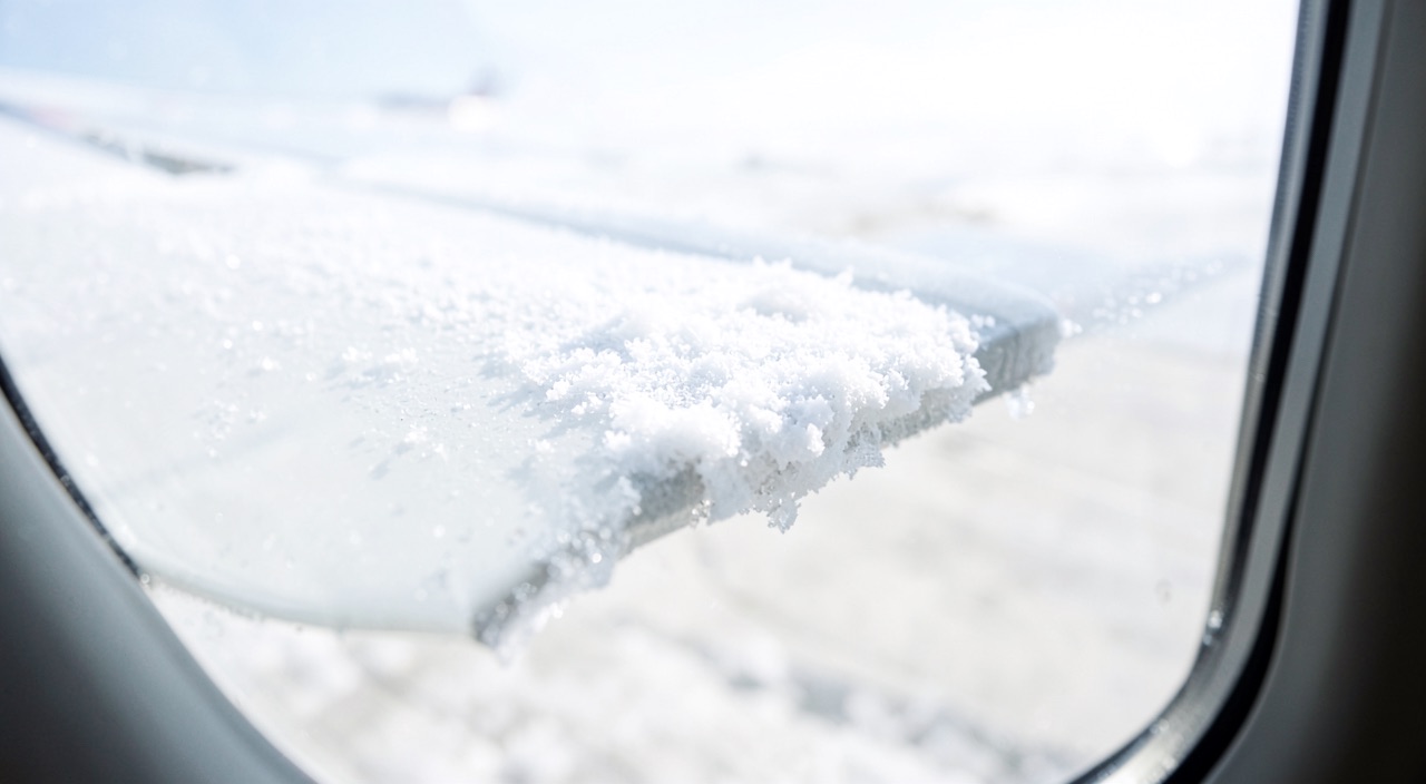
Extended hold in icing cloud, protection running, speed held to the knot by the autopilot: nothing moves. On the leading edge, a few tenths of a millimetre of granular deposit have settled exactly where the boundary layer is thinnest, and the stall angle of attack has receded by several degrees. The threshold that triggers the alarm, for its part, has not moved: it was set for a clean wing. The whole issue lies in that gap — nothing on board measures what remains, and the first sign may be a roll rather than a stick shaker.
The leading edge, where the wing has the least reserve
The flow wraps around the nose of the aerofoil, accelerates, reaches a suction peak within the first few percent of chord, then the pressure rises again toward the trailing edge. It is this pressure recovery that the boundary layer must cross while retaining enough momentum to stay attached. Maximum lift is therefore not fixed by the shape of the aerofoil but by the moment the boundary layer gives up: whatever depletes it upstream of the recovery moves that moment to a lower angle of attack.
Now it is near the peak that the boundary layer is thinnest, on the order of a fraction of a millimetre at the Reynolds numbers of an approach. A roughness of the same scale is not a surface blemish: it occupies a significant fraction of the local thickness, advances transition, thickens everything downstream, and the boundary layer arrives at the recovery already depleted. The wing has lost nothing of its geometry; it has lost the reserve that let it reach the last increments of lift.
This sensitivity depends on the aerofoil, which rules out transposing an experience from one type to another: a thin, heavily loaded aerofoil, whose stall initiates at the leading edge, loses its maximum lift abruptly and without an exploitable precursor, whereas a thick aerofoil separating from the trailing edge degrades progressively. On a slatted wing, with the slat extended, it is the nose of the slat that catches the droplets; with the slat retracted, accretion picked up in cruise ends up positioned differently in the flow at the next extension.
The wing’s leading edge is the most sensitive part to ice buildup. Even tiny roughness can disrupt airflow and reduce lift dramatically, but the aircraft’s systems won’t detect this until it’s too late.
Thickness is not the right criterion: relative height and location are
Intuition says a thick deposit should be worse than a thin one; for maximum lift, it is wrong. A layer of ice that is thick but conforms to the nose changes a shape: it shifts the suction peak and adds drag, but leaves the boundary layer a workable surface. A roughness of a few tenths of a millimetre changes the shape hardly at all and attacks the mechanism instead: the resulting loss of maximum lift is typically measured in tens of percent, and the recession of the stall angle in degrees. No general value transfers from one aerofoil to another, however: sensitivity is a property of the aerofoil and its loading, not a constant of icing.
Location matters just as much, and the decisive zone is short: the first few percent of chord, around the stagnation point and the upper-surface suction peak. The same ice further aft, where the boundary layer is already thick, costs little — except when it forms a ridge. A ridge does not degrade the flow, it separates it. And the threshold for visual detection remains well above the aerodynamic threshold: the costliest deposits are the least visible.
On an Airbus A320, a 0.3mm roughness on the leading edge can reduce maximum lift by 20%, while a 1cm smooth deposit might only reduce it by 5%. The tiny roughness is far more dangerous because it disrupts the critical boundary layer.
| Criterion | Fine distributed roughness | Thick, conforming deposit | Ridge or horn |
|---|---|---|---|
| Common origin | Onset of accretion, residue between two cycles, ground frost | Prolonged icing, protection inoperative | Refrozen runback, large supercooled droplets |
| Relative height and mechanism | On the same order as the boundary layer: thickens it before the recovery | Much greater: peak shifted, recovery made harder | Localised: clean separation behind the obstacle |
| Maximum lift and stall angle | Large loss for a negligible amount of ice; recession of several degrees | Loss proportional to the deformation; marked recession | Variable loss, abrupt behaviour |
| Controls and detectability | Indirect effect; near-invisible at night | Indirect effect; visible | Hinge moment altered; zone rarely visible |
Two curves deform, and the indicated speed does not move
In its linear portion, the lift curve versus angle of attack changes little; it is the peak that deforms — it drops and comes closer. For a given mass and configuration, the angle of attack required for level flight at a given indicated speed therefore stays unchanged: the aircraft flies as before, and what has been consumed is the gap between that angle of attack and the stalling one. One-g stall speed rises as the inverse square root of maximum lift — but no computer recalculates it against the real state of the surface, and the displayed low-speed band remains built on the clean wing.
The margin also closes from the other end: roughness increases drag markedly, and at constant thrust the aircraft slows down or descends. The first symptom is often an unusual thrust setting needed to hold speed and altitude. If the speed drifts, the angle of attack rises to meet a stall that has itself come down to meet it, and load factor accelerates everything: in a turn, in a pull-up, in a gust, the depleted margin is consumed in a fraction of the usual time — and at altitude, the low-speed buffet boundary rises as well.
Why the alarm can arrive after the wing already has
The stall warning is not a stall detector: it is an angle-of-attack threshold. Vanes measure a local angle of attack, compared against a threshold programmed by configuration and, depending on the type, by Mach number — a threshold derived from clean-wing testing, set back by an agreed margin below the measured stall angle. Nothing in it observes the state of the surface, and what follows is simple arithmetic: if the contamination removes from the stall angle as many degrees as the margin contained, the threshold ends up level with the actual stall, or beyond it. The alarm answers correctly a question that is no longer the right one.
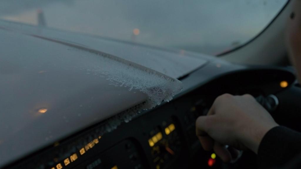
This is what the icing logics of recent types correct: accretion detected or protection running, the computer shifts the alarm threshold and raises the displayed minimum speeds. This shift is a design allowance, not a measurement — it is valid for the reference accretion adopted at certification. Nothing in it corresponds to undetected residual frost, to a ridge born of runback, or to accretion produced by droplets larger than those of the reference atmosphere — the SLD, subject to separate requirements.
The alarm has three further ways of arriving late, or not at all. The vane can ice over if its heating is insufficient, and the measured angle of attack becomes wrong, sometimes falsely low. Contamination can be asymmetric: the first event is a roll, not a stick shaker, which a control surface with an altered hinge moment can worsen. And the autopilot absorbs the growing force and trim that would have alerted a crew hand-flying, before handing the aircraft back at the end of its authority.
| Cue | What it actually shows | What it does not establish |
|---|---|---|
| Ice detector | An accretion on a probe: conditions exist | Neither the quantity, nor the roughness, nor the distribution across the wing |
| Ice evidence light | A thickness on an unprotected surface | Downstream of the protected zone, the tail |
| Stable indicated speed | The thrust-drag balance | The remaining margin, which erodes without changing the speed |
| Absence of buffet | That the separation is not beating on the structure | That the wing is far from the stall: the precursor may be absent |
| Silent stall warning | That the angle of attack stays below a clean-wing threshold | That the actual stall angle has not been reached |
| Leading edge seen from the flight deck | A portion of nose near the wing root, protected | The state of the aerodynamically decisive zone |
The trap. Taking the angle-of-attack alarm for the boundary of the manoeuvre. The habit of manoeuvring up to the stick shaker rests on a margin set for a clean wing; in icing air, that margin may have passed to the wing, and reaching the trigger amounts to reaching the stall. The corollary is more insidious: the absence of any sign — speed held, no buffet, no alarm — is the normal regime of a wing that has already lost a substantial share of its maximum lift.
What the protection covers, and what it leaves out
A protection system does not protect a wing: it protects a zone, defined at design for a reference icing envelope. Runback illustrates this: a thermal system that does not evaporate all the water it captures lets it flow aft, where it refreezes beyond the heated zone — where nothing was meant to receive it, and in the form most damaging to the controls. Cyclic pneumatic devices, for their part, leave a residue between two cycles: this intercycle accretion, accounted for at certification, is of the fine-roughness type, hence the costliest case for the smallest thickness. Not an anomaly, but the system’s normal state in service.
Large supercooled droplets shift the impingement zone aft: they settle beyond the protected leading edge, possibly near the aileron hinge line. The feared mechanism is no longer a loss of lift but a change in hinge moment strong enough for the control surface to move on its own, against the crew’s input. The tail follows the same reasoning, with a pitch signature and a recovery technique that can run counter to reflex.
The ground case is the same mechanism without the flight: hoar frost or cold-fuel frost, a few tenths of a millimetre on the upper surface, a ridiculous thickness with a very real effect, applied at takeoff when the margin is tightest. Hence the clean aircraft rule, which admits no adhering deposit whatever its thickness, and a tactile rather than visual check: a surface that looks wet can be rough and frozen.
The right reflex. Treat icing as a regime of speeds and margins, not as a switch: enter it as soon as the type’s criteria are met, without waiting for visual confirmation, and leave it only on the type’s exit criteria, which concern the confirmed absence of accretion, not the extinguishing of a light. Check accretion with the light on the designated cue, not on the leading edge as seen from the seat. And read the thrust needed to hold speed and level as the first indicator of surface condition.
The icing speed regime: what an increment actually buys
A speed increment restores no maximum lift: it lowers the operating angle of attack so that the stall angle, now lower, stays out of reach — a shift of the operating point, not a repair of the wing. It also sizes the manoeuvre margin and the buffet margin, hence its application to minimum holding and configuration speeds, and not only to the reference approach speed. It comes at a price: a faster approach, a longer landing, sometimes a limited high-lift configuration. Its value belongs to the type: it is read, not deduced.
The tricky question is not entering the regime, which costs little, but leaving it. The criterion is generally not the disappearance of the conditions but confirmation that the wing has become clean again, which presupposes an inspection of the cue and sometimes a delay. Leaving because the cloud has been left behind, while the deposit remains on an unheated surface, amounts to restoring clean-wing speeds on a wing that is not one.
What to check in your own documentation, and the grey area
Five points vary from one type to another and are found in the approved documentation: what triggers the icing regime; whether the computer shifts the alarm threshold and the minimum speeds, and on what event; the real extent of the protected surfaces, tail included; the high-lift configurations forbidden or required; the exit criteria, and what the minimum equipment list allows when a detector or a vane heater is missing.
The grey area will not close. No instrument measures the roughness present on the wing; certification bounds a reference accretion, not the day’s accretion. No display shows the remaining maximum lift: the one quantity that matters is the one that is not instrumented. Two habits remain worth drawing from this — treating accretion as present as soon as conditions make it possible, and reading required thrust as an indicator of surface condition.
For anyone preparing a type rating, two questions do not survive rote learning: why a fine, rough deposit costs more maximum lift than a smooth, thicker one, and why icing logic raises the speeds instead of lowering the alarm threshold. The reasoning is built better in training than by rereading a procedure, and entry and exit practices for the regime are compared on the FL330 professional forums.
The applicable regulations and the operator’s approved documentation — flight manual, operations manual, type procedures and limitations — prevail in all circumstances over this article, whose purpose is to explain a mechanism, not to serve as a procedure.
Questions fréquentes
Why does a roughness of a few tenths of a millimetre cost more maximum lift than a smoother, thicker deposit?
Because the two do not act on the same quantity. A thick but conforming deposit changes the shape of the nose, hence the pressure distribution, and costs lift roughly in proportion to the deformation. A fine roughness barely changes the shape but sits at the scale of the boundary layer, which is thinnest over the whole chord near the suction peak: it advances transition and thickens the boundary layer before the pressure recovery, so that it separates at a lower angle of attack. The relevant criterion is therefore not the absolute thickness of the deposit but its height relative to the local boundary-layer thickness, and its position within the first few percent of chord.
How can the stall warning trigger after the actual stall has already occurred?
The warning is not a stall detector but an angle-of-attack threshold, established through clean-wing testing by setting back an agreed margin below the measured stall angle. If the contamination removes from that angle a number of degrees on the order of the margin retained, the threshold ends up level with the actual stall or beyond it. The computer works correctly: it is the reference it was set against that no longer matches the wing. This is exactly why icing logics exist that shift the threshold and raise the minimum speeds — but that shift is sized for a reference accretion, not measured on the wing itself.
Is the ice detector enough to know whether the wing is contaminated?
No, and this limitation is structural rather than an installation weakness. A detector registers an accretion on a probe placed in a flow chosen at the design stage: it tells you that accretion conditions exist. It says nothing about the amount deposited on the wing, its roughness, its distribution across the span, or what has formed downstream of the protected zone or on the tail. The same caveat applies to the portion of leading edge visible from the flight deck, generally close to the wing root and generally protected, and therefore not representative of the aerodynamically decisive zone.
Why are icing speeds increased if maximum lift is lost anyway?
Because the increment does not restore maximum lift: it lowers the operating angle of attack so that the stall angle, now lower, stays out of reach. It also sizes the manoeuvre margin and the buffet margin, which is why it applies to minimum holding and configuration speeds and not only to the reference approach speed. The trade-off is a faster approach, a longer landing distance, and sometimes a high-lift configuration limited by the type’s documentation.
What is the tricky moment in the icing regime: entering it or leaving it?
The tricky moment is leaving it, with no real comparison to entering. Entering the regime costs little and is decided on condition criteria that are easy to confirm. Leaving it requires establishing that the wing has become clean again, which is not the same as having left the cloud: a deposit can remain on an unheated surface well after the conditions have ended. Restoring clean-wing speeds at that point amounts to applying clean-wing margins to a wing that is not one; the applicable criteria are those of the type, often coupled with an inspection of the cue and sometimes a delay.
Can accretion on unprotected surfaces affect the flight controls?
Yes, and it is one of the most feared scenarios of icing outside the reference envelope. Large supercooled droplets impinge further aft than droplets from the reference atmosphere and can form a ridge beyond the protected leading edge, possibly near the aileron hinge line. The separation that develops behind this ridge alters the control surface’s hinge moment, to the point where it can move on its own against the crew’s input. The mechanism is no longer a simple loss of maximum lift but a loss of handling quality, whose recovery technique belongs to the type’s documentation.


Leave a Reply
You must be logged in to post a comment.