
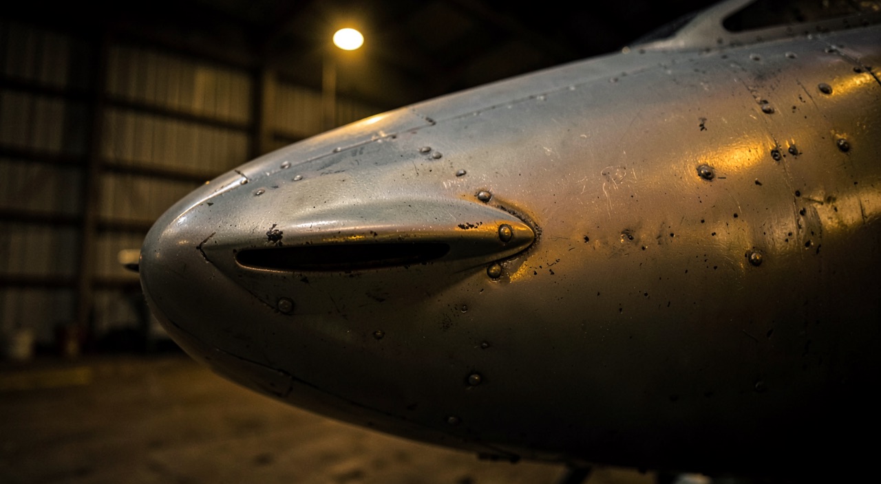
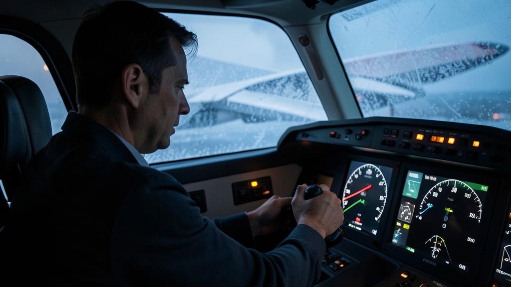
Holding, thirty degrees of bank, the airspeed needle comfortably above the reference speed displayed, the ice protection just selected: the stick shaker fires. Nothing has failed. The airspeed indication was telling the truth, and so was the warning — they simply are not talking about the same quantity. One reads a dynamic pressure, the other estimates an angle. As long as the flight deck reasons in speed, this trigger looks premature; the moment it reasons in angle of attack, it becomes the only reading consistent with the situation. What remains is to retrace the whole chain: what the wing actually experiences, what the vane detects, what the computer does with it, and why a stall speed is never anything but a tabulated consequence.
What the wing experiences: angle of attack versus lift
The wing has no speed sensor at all. What it experiences is a flow meeting it at a certain angle — the one formed by the relative wind with the reference chord — and a dynamic pressure. For a given airfoil and configuration, the lift coefficient depends only on that angle and on the Mach number. The relationship starts out nearly linear: each additional degree of angle of attack adds a fairly constant share of lift, because the stagnation point moves below the leading edge, the upper-surface overspeed increases, and the resulting suction spreads. Then the curve bends over. The adverse pressure gradient prevailing behind the suction peak becomes too steep for the boundary layer, which separates: first over a small area, then over a growing one.
The peak of that curve is the only physical benchmark that matters, and it is the stall angle of attack. Beyond it, one more degree no longer produces lift, it destroys it. This point is not a cliff but a rounded summit, and what happens around it is a matter of wing geometry: washout, taper, high-lift devices, vortex generators, stall fences. A separation that begins at the wing root stays symmetric, predictable, and the disturbed flow sweeping the tailplane announces itself through a characteristic buffet. A separation that begins at the wingtip rolls the aircraft and strips the ailerons of their authority at the very moment it is most needed. Hence the effort manufacturers put into provoking the first rather than the second, and hence the fact that a stall warning is a certification requirement, not a convenience.
Three immediate consequences, often absent from flight-deck reasoning. Mass does not enter the relationship between angle of attack and lift coefficient; neither does altitude, as long as one stays far from compressibility effects. Leading-edge contamination, by contrast, enters it abruptly: roughness or an accretion moves the separation forward, lowers the achievable maximum, and lowers the angle at which that maximum occurs. As for load factor, it does not enter it either: it is not the g that stalls a wing, it is the angle of attack that must be reached to produce that g.
The wing doesn’t care about speed—it only knows the angle of the air hitting it. When that angle gets too steep, the air stops flowing smoothly, and the wing loses lift. Ice or dirt on the wing makes this happen earlier and more suddenly.
An Airbus A320 at 30,000 feet in a 45° bank turn (1.4g) will stall at about 120 knots instead of 100 knots in straight-and-level flight. The wing’s angle of attack is the same in both cases—it’s just that the higher load factor demands more speed to maintain lift.
Stall speed is only a tabulated line
What remains is to state what the flight deck actually uses. In steady flight, lift balances weight; more generally, it equals weight times the load factor. Since lift is also the product of dynamic pressure, reference area and lift coefficient, replacing that coefficient with its maximum yields the lowest speed at which flight remains possible under those conditions. This speed is therefore an output of a calculation, not a property of the airframe: it depends on mass, load factor, configuration, and — for true airspeed — on air density.
Hence the regularities everyone handles without always seeing where they come from. Stall speed varies as the square root of mass: ten percent more mass, about five percent more speed. It varies as the square root of load factor: in a symmetric thirty-degree bank turn, the load factor is about 1.15 and stall speed increases by about seven percent; at sixty degrees it is two and stall speed increases by about forty-one percent. The margin one believed held in straight flight is therefore consumed in the turn without the needle moving a single knot. A vertical gust produces the same effect in a fraction of a second, and without any pilot intent.
Transport aircraft certification, moreover, stopped speaking of a single stall speed long ago. It defines a reference stall speed, anchored to the maximum lift obtained in a one-g maneuver, for a given mass, center of gravity and configuration, then builds the operational speeds as multiples of that reference — factors typically between 1.1 and 1.3 depending on the flight phase. The manual thus publishes a family of lines, each valid under explicit assumptions. Reading one of these lines as « the aircraft’s stall speed » is the original error: it confuses a tabulated value with the phenomenon it indexes.
| Parameter changed | Effect on stall speed | Effect on stall angle of attack |
|---|---|---|
| Higher mass | Increases as the square root of mass | Unchanged |
| Load factor (turn, pull-up, gust) | Increases as the square root of load factor | Unchanged, but reached earlier |
| Lower density (altitude, warm air) | True airspeed higher; indicated airspeed essentially unchanged | Unchanged as long as Mach number stays moderate |
| High Mach number | Rises: the exploitable lift maximum decreases | Decreases: shock-induced separation precedes the low-speed stall angle |
| Leading-edge slats extended | Falls | Increases: separation is pushed to larger angles |
| Trailing-edge flaps extended | Falls | Generally lower for the aircraft, camber doing the work instead of angle |
| Ice, roughness, contamination | Rises, by an unguaranteed amount | Decreases, by an unguaranteed amount |
| Forward center of gravity | Rises slightly, trim download having to be compensated | Unchanged for the wing |
What the vane detects, and what it does not
The angle-of-attack sensor is a modest object: a free-rotating vane mounted flush with the forward fuselage skin, which aligns itself with the local flow and transmits its angular position. Some types use a slotted probe or a differential pressure measurement; the principle does not change. What this object measures must be stated without indulgence: the angle of the local flow, at its station, in a field already disturbed by the nose. It is not the angle of attack of the wing, and it is not even the angle of attack of the aircraft.
Between the two lies a calibration. The law relating the angle read to the aircraft’s angle of attack is established in wind-tunnel and flight testing, then applied on board with corrections: Mach number effect, high-lift device position, landing gear position, and sideslip — because a sensor mounted on the left and one mounted on the right do not see the same flow when the aircraft flies with sideslip, so comparing the two channels tells as much about sideslip as about angle of attack. This calibration chain explains why an angle-of-attack value only makes sense on its own type, and why no angle-of-attack figure carries over from one type to another: the same flight angle produces different readings there.
The rest is a matter of installation and maintenance. The vanes are heated, on pain of freezing in some arbitrary position in icing conditions — and a jammed vane does not fail outright, it lies consistently. They are redundant, and the computer arbitrates by comparison or by voting: two channels allow a disagreement to be detected, three allow the faulty channel to be discarded. Finally, their angular reference is mechanical. A bird strike, a skin repair, a reassembly after painting, excess paint around the slot can introduce a permanent bias that triggers no crew message and yet shifts the entire alerting schedule.
The mechanical zero is not the aerodynamic zero
Hence the nature of the maintenance tasks attached to these sensors: rigging check against a template, verification of free rotation and damping, check of the heating, surface condition of the surrounding area. These are geometry tasks, not electronics, and they are re-required every time the nose is opened, repaired or repainted. A system that is perfectly sound electrically can therefore alert at the wrong moment, or worse, alert too late.
The trap: the alarm judged premature, and therefore treated as spurious. After ice protection selection, or upon ice detection, many types deliberately lower the trigger threshold, since contamination lowers the stall angle of attack. The shaker can then fire at an indicated airspeed the crew associates with a perfectly healthy flight, and one that sits above the low-speed reference memorized for the configuration. Countering this trigger by pulling to hold altitude is to go and fetch exactly the angle of attack the alarm is signaling has become reachable. The same reasoning holds in a turn and in turbulence: the threshold itself has not moved — it is the flight angle of attack that has risen.
What the alarm actually computes
A stall warning does not announce a stall: it announces the exhaustion of an angle-of-attack margin. The computer has the estimated angle of attack and a trigger angle-of-attack schedule, a function of configuration and Mach number, and it fires when the first approaches the second. Two refinements matter operationally. The first is a rate-of-change term: an angle of attack rising fast will be exceeded before the crew has reacted, so the threshold is advanced in proportion to the rate — which is why a brisk pull-up triggers earlier than a slow deceleration at an identical instantaneous angle of attack. The second is the icing bias, applied depending on type either on actual detection or on mere selection of the protection systems.
The output depends on type. A stick shaker provides a tactile and audible warning that nothing masks, which is precisely the intent: it does not ask to be read. A stick pusher goes further and imposes the angle-of-attack reduction. On certain fly-by-wire architectures, the logic changes in nature: angle of attack becomes a controlled quantity, bounded by protections, and the stick input becomes more of a load-factor request than an attitude request. Until the moment the degradation of those protections abruptly hands back to the pilot a responsibility he had delegated without thinking about it, often together with a doubtful airspeed indication.
What remains is the argument that alone justifies reasoning in angle of attack: robustness to failure. An indicated airspeed depends on the total pressure port and the static reference. A blocked port, a damaged radome, ice frozen in a line produce a false airspeed, sometimes plausible, sometimes consistent across several channels when the cause is common — the worst of cases, since comparison detects nothing. Angle of attack, on the other hand, comes from a physically independent chain. This is what allows certain types to offer a backup speed scale built entirely on angle of attack, and this is what makes the stall warning credible at the very moment the airspeed indication no longer is.
Two regimes the flight deck still confuses
An approach-to-stall warning and an established stall do not call for the same response, and treating them the same way was long taught. The reflex inherited from older training sessions — hold altitude, add thrust, wait for the speed to come back — works as long as the margin is only partly eaten into. Applied to a wing whose flow has already given way, it makes things worse: thrust from engines mounted under the wing creates a nose-up moment, and any action aimed at not losing altitude is a nose-up action, hence an increase in angle of attack. The overhaul of loss-of-control prevention and recovery training programs consisted precisely in separating these two regimes and making angle-of-attack reduction the first action in both cases.
| Element | Approach to stall (margin partly eaten into) | Established stall (lift lost) |
|---|---|---|
| Available cues | Shaker, low-speed indication, possible onset of buffet | Established buffet, sink, degraded roll authority, pitch no longer commanding the trajectory |
| First action | Give back angle of attack by relaxing the nose-up input | Reduce angle of attack firmly and without hesitation, until symptoms disappear |
| Altitude | Generally tenable once angle of attack has been given back | Loss to be accepted as a condition of recovery |
| Thrust | Useful addition to rebuild energy | To be managed carefully: nose-up moment of underwing engines, delayed response |
| Roll | Normal correction on the ailerons | Ailerons of little effect and potentially aggravating as long as angle of attack is not reduced |
| Trim | Rarely at fault | Position to check: a nose-up trim left set will reinstate angle of attack as soon as the input is relaxed |
| Exit | Return to the intended trajectory | Wings-level recovery, then a progressive climb-out without reinstating angle of attack |
The right reflex: state the priority in the order aerodynamics imposes it — give back angle of attack first, manage energy next, recover altitude last. In practice this means relaxing back pressure or pushing before thinking about the thrust levers, and treating altitude loss as the price paid rather than as a mistake to avoid. The same statement serves as a reading grid for simulator sessions: a recovery that cost nothing in altitude probably did not handle a stall, but an approach to stall — useful, but not the same exercise.
At high altitude, the angle-of-attack margin becomes a maneuvering margin
Near the ceiling, two phenomena converge. From below, the angle of attack needed to sustain the mass increases as density decreases. From above, the high Mach number brings on shock waves whose foot causes local separation, so that the exploitable lift maximum decreases and the angle at which buffet appears comes down. The window between the two closes. It is this window that manufacturers translate into a maneuvering margin: the load factor available before buffet onset, for a given mass and level.
The consequences are concrete. An optimum level is not a ceiling level, and between the two the maneuvering margin thins to the point that turbulence, a steep turn or a brisk correction is enough to consume it. Available excess thrust is small, so a deceleration can no longer be recovered quickly: returning to a comfortable maneuvering speed is paid for in time or in altitude, not in thrust. Reference cues also change: depending on type, buffet can manifest before the angle-of-attack warning, and read as light turbulence when it is in fact signaling that the upper surface is starting to give way. A climb accepted by the flight management computer is not therefore a climb that leaves any margin once stabilized, especially if temperature departs from the standard model.
What to check in one’s own documentation, and the gray area that remains
Five points are found in one’s own documentation rather than in a memory of ground school. On what basis the manual’s speeds are established — one-g stall or dynamic stall — and under what assumptions of mass, center of gravity and configuration. How the type’s alert schedule is biased in icing conditions, and what triggers that bias: actual detection, selection of a system, or a temperature-and-visible-moisture combination. What the minimum equipment list items allow in the event of losing one angle-of-attack channel, and what that loss removes from the protections. Which low-speed indications on the speed tape are derived from angle of attack and which are computed from the entered mass — the two do not behave the same way when a piece of data becomes false. Finally, which maintenance tasks cover sensor rigging, so as to know what must be redone after work on the nose.
The gray area lies in what is not displayed. Many transport flight decks do not present angle of attack permanently: the information exists, it feeds the alarms and the protections, but the crew only reads it indirectly, through a speed and color bands derived from it. The debate on permanent display is not settled, and it pits two real costs against each other: one more quantity to interpret under high workload, versus direct access to the one variable the wing actually knows. For anyone preparing a type rating or a technical check, this is exactly where the expectation lies. Reciting a stall speed proves nothing, since that speed depends on conditions the examiner can change with a single sentence. What does prove something is the reverse path: from angle of attack to speed, from sensor to schedule, from schedule to the first action and to what it costs. This reasoning is worked through in training and tested against real cases on the forum.
The applicable certification and operating texts, the type’s flight manual and the operator’s approved documentation prevail in all circumstances over this article, whose purpose is to explain a mechanism, not to serve as a procedure.
Questions fréquentes
Why does stall speed change while the stall angle of attack does not?
Because these are two quantities of a different nature. The stall angle of attack is an aerodynamic property of the wing in a given configuration: it depends neither on mass nor on load factor. Stall speed, by contrast, is the result of an equilibrium calculation between required lift and the lift available at the maximum coefficient; it therefore moves as soon as mass, load factor, configuration or density change. A published speed is only valid under the assumptions that accompany it.
The shaker fired at a speed noticeably higher than expected: should a sensor failure be suspected?
Not at first. Two normal causes explain most of these cases: a load factor above one, in a turn, a pull-up or turbulence, which raises stall speed without the angle-of-attack threshold having moved; and the icing bias, which deliberately lowers the trigger threshold as soon as the protection is selected or ice is detected. In both situations, the handling stays the same: give back angle of attack, then analyze. A genuine sensor anomaly is then investigated, based on channel disagreement and the history of work on the nose.
What exactly does an angle-of-attack vane measure?
It measures the angle of the local flow at its fuselage station, not the angle of attack of the wing nor that of the aircraft. A calibration established in wind-tunnel and flight testing converts this local angle into aircraft angle of attack, with corrections for Mach number, high-lift device position, landing gear and sideslip. This is why an angle-of-attack value does not carry over from one type to another, and why a mechanical bias in the sensor silently shifts the entire alerting schedule.
Why accept a loss of altitude during a stall recovery?
Because any action aimed at holding altitude is a nose-up action, hence an increase in angle of attack — exactly the opposite of what must be done once the flow has given way. Lift is only rebuilt by bringing angle of attack back below the stall angle, which requires letting the flight path dip downward for as long as needed. Loss of altitude is not a regrettable consequence of the recovery: it is its condition.
Why is angle-of-attack information more robust than speed in case of unreliable airspeed?
Because the two chains are physically independent. An indicated airspeed depends on the total and static pressure ports, which are sensitive to blockage, icing and radome damage, with a risk of common-cause failure across several channels. Angle of attack comes from separate sensors, mounted elsewhere and driven differently. This is what allows certain types to build a backup speed scale directly on angle of attack, and what makes the stall warning usable at the very moment speed stops being so.
What is called the maneuvering margin at high altitude, and why does it narrow?
It is the load factor available before buffet onset, for a given mass and level. It narrows from both sides: low density forces flight at a higher angle of attack to sustain the mass, while the high Mach number brings on shock-induced separation that lowers the angle at which buffet manifests. Since excess thrust is limited at these levels, a deceleration can no longer be recovered quickly, and a steep turn or turbulence can consume what margin remains.


Leave a Reply
You must be logged in to post a comment.