
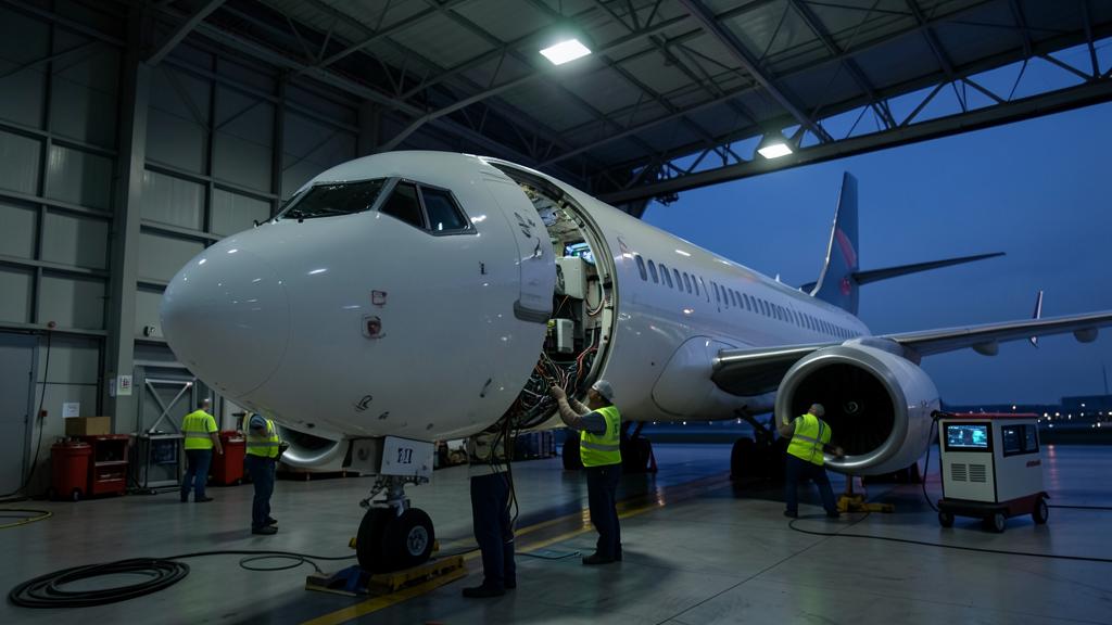
A cabin retrofit is signed off in a hangar, on ground power, with the doors open and nothing transmitting for real. The equipment arrives qualified, the installation is inspected against approved data, the systems power up, and no anomaly is observed. Then the aircraft goes back on line and a crew reports a satellite count that drops in the cruise, or an HF noise floor that has risen since the modification. Nothing was done badly. The test simply asked a question the hangar cannot answer.
Qualification proves the box, the aircraft proves the installation
Equipment-level qualification under RTCA DO-160, or its European equivalent ED-14, establishes that a unit emits below defined limits and keeps working when it is illuminated, when its power input is disturbed, when a lightning-induced transient arrives on its harness, and when it is discharged into. That work is done on a bench, with a defined ground plane, a defined harness length and a defined load. It is necessary and it is not the aircraft.
What a retrofit changes is the installation: where the harness runs, what it runs beside, how the shields are terminated, where the return current goes, what the new antenna sees, and which of the existing systems now shares a bus or a raceway with something that did not exist last week. None of those variables were present on the bench, and most of them cannot be exercised at their real values with the aircraft on jacks in a hangar.
The regulatory frame separates the two questions in the same way. The design change is approved under the applicable airworthiness code, which requires the aeroplane’s electrical and electronic systems to tolerate the high-intensity radiated field and lightning environments at aircraft level, and to remain compatible with each other in the installed configuration. The embodiment is then carried out and released by a maintenance organisation working to the approved data. Compliance at aircraft level is a demonstration, not an inference from the qualification certificates in the box.
The electrical environment on the ground is a different environment
A ground cart is a well-behaved, low-impedance source at a fixed frequency. Engine-driven generation is not. On the many modern types with variable-frequency AC systems, the frequency moves with engine speed across a wide band, so any resonance, filter corner or beat product that depends on line frequency simply does not occur at the value the cart supplies. Source impedance, harmonic content, transient behaviour on transfer, and the ripple riding on the direct-current buses all differ between cart, APU and engine-driven generators.
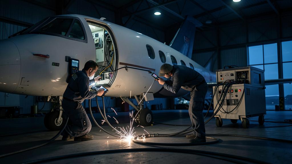
The structural reference differs too. On the ground the aircraft has a leakage path to earth through its conductive tyres, and in many procedures a deliberate one through a grounding cable. In flight it floats. Common-mode currents that had a comfortable path to earth now have to circulate in the airframe, and the new bonding straps installed for the retrofit become part of that circuit rather than a formality on an inspection card.
Load conditions are the third difference. Retrofit cabin systems reach their real duty cycle only with a full cabin: seat power supplies near their maximum, an in-flight entertainment server streaming to every seat, a connectivity terminal transmitting continuously with its antenna tracking, galley loads cycling. On the ground the terminal may not even acquire the satellite at that elevation, which means the largest deliberate emitter on the aircraft is tested in the one state where it is quiet.
| Parameter | On the ground | In flight | Why it matters |
|---|---|---|---|
| Power source | Cart or APU, fixed frequency, low impedance | Engine-driven generation, frequency varying with engine speed on variable-frequency systems | Frequency-dependent resonances and filter behaviour never appear at the cart’s frequency |
| Structural reference | Referenced to earth through the tyres and the grounding cable | Floating, charging and discharging through the static dischargers | Common-mode return paths change; new bonding straps become live circuit elements |
| Emitter duty cycle | Standby, low power, terminal often unable to acquire | Continuous transmission at operational power, antenna tracking through attitude changes | The dominant intentional emitter is only exercised airborne |
| Cabin load | A handful of technicians, seat power idle | Full seat power draw, server at capacity, hundreds of personal devices | Conducted noise on the shared buses scales with the load that is absent on the ground |
| External environment | Partially shielded by the hangar, few illuminators | Line of sight to ground radars and broadcast transmitters, changing geometry | Aircraft-level susceptibility depends on illumination the hangar removes |
| Airframe state | Cold, static, freshly assembled | Vibration, thermal cycling, pressurisation, precipitation | Shield terminations and connector contact resistance degrade only under those cycles |
Precipitation static does not exist in a hangar
An airframe flying through cloud, ice crystals or dust accumulates charge, and the charge leaves through the static dischargers if the bonding network is sound, or through corona at any other point if it is not. The resulting broadband noise is a classical cause of degraded HF and VHF reception, wandering automatic direction finder bearings and reduced satellite navigation margin. It is entirely a flight phenomenon: no charge accumulates on a bonded aircraft in a hangar.
Retrofits interact with it in two ways. New apertures — an antenna cutout, a modified radome, a replaced window panel — change where charge concentrates and where it can leave. And any work that disturbs the bonding network, the dischargers or their attachment points changes the discharge path. A precipitation static problem introduced by a modification will pass every ground test that exists, then present itself as an intermittent radio complaint months later, in weather, at a specific stage of flight.
The coupling paths that only close in the air
Interference needs a source, a path and a victim. Retrofits are generous with sources and victims; what decides the outcome is the path, and paths are properties of the installed aircraft.
Conducted coupling happens on shared power buses and shared returns. A switching supply for seat power or a lighting driver puts noise onto the bus it feeds, and the victim is anything else fed from the same bus with insufficient filtering. Radiated coupling happens where the new harness runs alongside a legacy loom in a common raceway, and it is dominated by the length of the parallel run and by the quality of the shield termination. A shield returned through a long pigtail stops behaving as a shield above a certain frequency, because the inductance of the pigtail comes to dominate the termination, and what was meant to contain the noise starts to radiate it.
Antenna-to-antenna coupling is the front door. A new blade or plate antenna sits at a defined distance from existing ones, in a pattern that is modified by the structure around it and by the aircraft’s attitude. Satellite navigation is among the most exposed victims on the aircraft, because it works with a received signal below the thermal noise floor: a broadband emitter needs to raise that floor only slightly to remove margin, and it does so silently. Intermodulation belongs in the same paragraph. Several transmitters running simultaneously at operational power produce mixing products that exist only when they are all transmitting at once, which is a state that occurs in the cruise and essentially never in a hangar.
| Mechanism | Why a ground test misses it | What exposes it |
|---|---|---|
| Conducted noise on shared buses | Cabin loads idle, generation supplied by a clean cart | Full cabin load on engine-driven generation, with power quality recorded at the victim |
| Harness-to-harness crosstalk | New systems in standby, shield terminations not yet vibrated | New systems at maximum duty, after several flight cycles |
| Antenna-to-antenna coupling | Terminal not transmitting, pattern altered by hangar structure | Transmit at operational power through the attitude range, monitoring victim signal quality |
| Intermodulation between transmitters | Transmitters rarely active simultaneously on the ground | All emitters on, in every combination, with victims instrumented |
| Precipitation static | No charging occurs on a grounded aircraft | Flight in precipitation or ice crystals, monitoring HF and VHF noise and satellite navigation |
| External field illumination | Hangar attenuates, geometry fixed | Low-level flight and approach near known emitters, in the real geometry |
The victims degrade, they do not fail
The single most damaging assumption in a retrofit test plan is that interference announces itself. It rarely does. A navigation receiver that loses a few decibels of carrier-to-noise density still navigates; it simply has less margin, tracks fewer satellites, and loses integrity availability sooner in a degraded constellation geometry. A communications receiver with a raised noise floor still works; the squelch just breaks more often and the crew blames the frequency. An automatic direction finder wanders. A radio altimeter behaves normally except in a narrow set of conditions.
That last case is the reminder the industry has worked hardest on lately: what a receiver tolerates from emitters outside its own band is an aircraft-level and operational question, not one the bench settles. The lesson generalises: if the acceptance criterion for a modification is « no anomaly reported », the test has no resolution, because the failure mode being sought is a reduction in margin that no cockpit indication displays.
The trap. « No anomaly observed » is not a measurement. It is the absence of one. An electromagnetic compatibility test plan that produces narrative conclusions rather than recorded quantities cannot detect the degradation it exists to find, and it will pass a modification that has already consumed the margin of a receiver the crew depends on in the approach.
The baseline is what makes every later measurement mean something
Degradation is a difference, and a difference needs two terms. The pre-modification measurement on that specific airframe is therefore the highest-value item in the whole exercise, and it is the one most often skipped because the aircraft is already in the hangar and the schedule is tight.
The baseline should be recorded in flight, not only on the ground, and it should capture the quantities that will later be compared: satellite carrier-to-noise density and satellites tracked by phase of flight, the received noise floor on the communication receivers in use, bonding resistance at the interfaces that will be disturbed, and power quality at the buses that will carry the new loads. Fleet variability makes this specific rather than generic: an installation embodied on twelve aircraft can behave differently on the thirteenth because a bundle was routed on the other side of a frame, and only a per-airframe baseline exposes that.
Building a flight test matrix that can actually fail
A useful matrix crosses three axes: the state of the new system, the victim being monitored, and the condition of the aircraft. It is built so that a negative result is possible, which means each cell has a recorded quantity and a threshold agreed in advance.
| Axis | States to cover |
|---|---|
| New system | Off, powered but not transmitting, transmitting at operational power, maximum cabin load, and every combination of simultaneously active emitters |
| Victims monitored | Satellite navigation carrier-to-noise density and satellite count, VHF and HF noise floor, automatic direction finder bearing stability, radio altimeter, transponder and traffic system, weather radar, autopilot and flight director behaviour |
| Flight phase | Ground runs on each electrical configuration, climb, cruise, descent, approach and go-around, with the approach flown on the guidance actually used in service |
| Electrical configuration | All generators on line, a single generator supplying the aircraft, APU supply, and the emergency or battery configuration in which load shedding changes the bus topology |
| Environment | Clear air and, where achievable, precipitation or ice crystal conditions for the precipitation static case |
Two disciplines make the matrix worth flying. Everything is time-stamped against a single clock, so a satellite count drop can be correlated with the moment a transmitter changed state; crew recollection cannot do this. And the switching sequence is scripted, so the aircraft spends time in each state rather than passing through it. An instrumented, scripted flight of a couple of hours will find more than a month of unstructured line service.
Return to service starts the surveillance, it does not end the work
Some mechanisms are conditional on weather, geometry or a combination of emitters that a test flight will not reproduce. That is not a reason to fly more test hours; it is a reason to define what happens after the certificate of release to service.
Three things belong in that definition. A surveillance window of a stated length, during which the modified aircraft is watched. A specific question put to crews, because « anything unusual? » produces nothing while « any degradation of satellite navigation, VHF or HF with the new system transmitting? » produces usable reports. And a rollback criterion agreed before it is needed, with the configuration control to apply it, so that a fleet campaign is paused rather than completed while a signal is being investigated. The engineering culture that supports this kind of reporting is discussed at length on forums.fl330.com.
The right habit. Record the pre-modification baseline in flight, on the actual airframe, before the first panel comes off. It costs one sector of instrumented data and it converts every later measurement from an opinion into a delta. Without it, the only available conclusion after the modification is that the systems appear to work — which was never the question.
What this changes in practice
The ground test keeps its role. It confirms the installation matches the approved data, that bonding and shield terminations are as designed, that the loads behave, and that nothing gross has been created. What it cannot do is exercise the coupling paths, because those close only when the aircraft is on its own generation, floating electrically, fully loaded, transmitting for real and flying through weather.
The practical shape of a defensible plan is short. Baseline before, on the airframe and in flight. A scripted, instrumented flight matrix built so that failure is detectable. Acceptance criteria expressed as recorded quantities against that baseline. And a surveillance window with a defined question and a defined rollback. Everything else is documentation.
The hangar can’t fully test how new equipment will work in flight because the real-world conditions—like power sources, electrical loads, and weather—are different. Ground tests miss key issues like interference between systems or how antennas interact in the air. To properly check a retrofit, you need to test it in actual flight conditions, not just in a hangar.
On an Airbus A320, a retrofit of the in-flight entertainment system caused satellite navigation issues. Ground tests showed no problems, but in flight, the satellite count dropped when the new system transmitted at full power. The issue was caused by antenna-to-antenna coupling, which only appeared when the aircraft was airborne and the systems were operating at full capacity. The problem was fixed by adjusting the antenna placement and adding shielding.


Leave a Reply
You must be logged in to post a comment.