
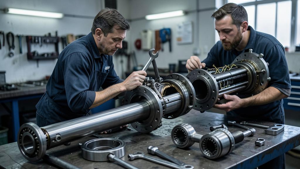
Whether a large turbofan turns on two shafts or three was decided by aerodynamicists, decades ago, for reasons that have nothing to do with maintenance. The shop pays for that decision every day: in bearing compartments, in the order modules come apart, in how many rotors have to be balanced and in what a technician can reach without a full strip. This is the line that runs from a compressor matching problem to a workscope decision.
Why there is more than one shaft at all
A compressor stage works well over a narrow band of blade speed and inlet conditions. Stack many stages on one shaft and they are forced to turn together, which means that at any operating point away from the design point some stages are working hard while others are close to stalling. The front stages want to turn slowly; the rear stages, working on hot, dense, already-compressed air, want to turn fast. A single shaft cannot give both what they want.
Splitting the compression into a low-pressure spool and a high-pressure spool lets each turn at a speed that suits its own stages, and each is driven by its own turbine. That is the two-spool architecture used by the great majority of large commercial turbofans. It does not remove the matching problem entirely — it makes it tractable — and the remaining mismatch is handled with variable geometry: variable inlet guide vanes and variable stator vanes that reset the incidence onto the rear stages, plus bleed valves that dump air overboard at low power to keep the front stages breathing.
Adding a third, intermediate-pressure spool takes the idea one step further. Each of the three now turns nearer its own optimum, which allows the same overall pressure ratio with fewer stages and reduces how much variable geometry is needed to hold surge margin. That is the reasoning behind the three-shaft family that Rolls-Royce has built since the RB211 and continued through the Trent engines. A fourth answer exists and is not a spool at all: a reduction gearbox between the fan and the low-pressure turbine, letting the fan turn slowly while its driving turbine turns fast, as on Pratt & Whitney’s geared turbofans.
What an extra shaft costs mechanically
Three shafts on a common axis are concentric, and geometry sets the order. The low-pressure shaft is the longest: it runs innermost, from the fan at the front to its turbine at the far end of the engine. The intermediate shaft is a hollow drum around it, and the high-pressure shaft — the shortest of the three — a shorter drum outside that again. Every shaft needs its own bearings, every bearing needs oil supply and scavenge, and every bearing compartment needs seals that hold pressurised air out of an oil space and oil in. Oil lines and scavenge returns have to be routed through structural struts, because there is nowhere else to cross the gas path.
None of this is exotic engineering, but it is cumulative. A shaft added for aerodynamic reasons brings bearings, compartments, seals, oil paths and a further set of vibration modes with it. It also changes what can be taken apart without disturbing what sits inside it — which is where the shop stops being an interested observer and becomes the party that pays.
| Architecture | Aerodynamic effect | Mechanical consequence | What the shop sees |
|---|---|---|---|
| Two spools | Matching held by variable stators and bleed valves | Fewer shafts, bearings and seals; more variable geometry hardware | Simpler rotor stack; recurring work on actuators, unison rings and bushings |
| Three spools | Each spool nearer its optimum speed; fewer stages for the same pressure ratio | Concentric shafts, more bearing compartments and seals, more rotor systems | More rotors to balance; access sequence constrained by what runs inside what |
| Geared fan | Fan and its driving turbine decoupled in speed | A reduction gearbox in the load path, with its own oil and thermal management | A gearbox as an inspection and life item in its own right |
Modules, and why they are the real unit of work
No large engine is treated as one object in the shop. It is a set of modules — fan and low-pressure compressor, intermediate compressor where one exists, high-pressure compressor, combustor, high-pressure turbine, low-pressure turbine, accessory drive — each of which can in principle be removed, exchanged and returned to service with its own paperwork.
Modularity is what makes a targeted shop visit possible. If the deterioration is in the hot section, the workscope opens the hot section and leaves the rest closed; if a compressor has ingestion damage, that module is addressed. This is also what allows an engine to be returned to service with a module that has a different history from its neighbours, which is why the critical parts are tracked individually rather than by the engine they happen to be fitted to.
Architecture sets the boundaries of that freedom. A module cannot be removed without disturbing whatever passes through it, and on a concentric three-shaft engine the innermost shaft is, by definition, inside the others. The result is not that three-shaft engines are harder to maintain in some general sense — it is that the sequence of operations is more constrained, and a shop that does not plan the sequence loses time it cannot recover.
Balancing: one rotor is a task, several are a discipline
Rotating assemblies are balanced at several levels, and each level exists because the one before it is not sufficient. Individual discs and blisks are balanced as components. Blades are distributed around a disc by mass so that the assembled stage is balanced rather than merely built from balanced pieces. Stages joined by curvic couplings can be stacked at different relative angles, and choosing those angles is an optimisation, not an assembly detail.
Built rotors are then balanced as assemblies, and where the manual calls for it this is done at representative speed rather than slowly, because a rotor that is balanced at low speed is not necessarily balanced when it has grown thermally and deflected under its own centrifugal load. Finally, the engine on wing can be trim balanced: a vibration survey identifies the residual and correction masses are applied at an accessible plane, typically on the fan.
The arithmetic is unforgiving. Each additional spool adds a complete rotor system with its own balance requirements, its own stacking decisions and its own vibration signature. Whatever the architecture, the discipline is the same; the volume of it is not.
The trap. Trim balancing on wing corrects a residual imbalance. It does not correct a rotor that is out of balance because it was stacked badly, a blade set that was redistributed incorrectly, or a bearing that is failing. A vibration level that keeps returning after successive trim balances is telling you the correction is being applied at the wrong level — and continuing to add mass to the fan buries the evidence instead of finding the cause.
More shafts mean more moving parts to balance and maintain. Each extra spool adds complexity, requiring careful sequencing during repairs. The shop must plan carefully to avoid costly mistakes.
On a Rolls-Royce Trent 900 (three-spool), the shop must first remove the fan module to access the intermediate-pressure compressor, then disassemble the high-pressure spool. A misstep here could force a full strip, adding 50+ hours of labor and $100,000 in costs.
What the shaft count changes on the flight deck and at the line
A two-spool engine reports two rotor speeds; a three-spool engine reports three. That is not cosmetic. Each spool has its own vibration signature, and a broadband vibration indication that means one thing on a two-shaft engine has to be attributed to a specific rotor before it means anything on a three-shaft one. Trend monitoring systems separate the signatures precisely so that a rising level can be attributed rather than merely noticed.
| Indication | What it reflects | What it does not tell you alone |
|---|---|---|
| Rotor speeds, one per spool | The operating point of each spool independently | Which spool a vibration originates from, unless the signature is separated |
| Vibration level, per rotor where available | Residual imbalance and its trend | Whether the cause is imbalance, a bearing, or rubbing |
| Exhaust gas temperature margin | Cumulative deterioration of the core, chiefly tip clearances and seals | Which module has deteriorated |
| Oil consumption and oil system indications | Behaviour of the bearing compartments and their seals | Which compartment, without further inspection |
| Borescope findings | Condition of specific stages, on wing, without a strip | Anything outside the ports’ field of view |
Borescope inspection deserves emphasis because it is the main defence against unnecessary removal. Access ports allow specific stages to be examined with the engine installed, and a large part of continuing airworthiness on modern engines rests on a scheduled inspection programme that keeps engines on wing until there is a reason for them not to be. The architecture determines what can be seen through those ports and what cannot, which is another way of saying it determines when the shop gets involved at all.
Life-limited parts run on cycles, and they do not care about modules
Critical rotating parts — discs, shafts, spacers, hubs — carry an approved life expressed in cycles, and they are tracked individually. The remaining life of a part is a property of that part, follows it into whatever engine it is fitted to, and is unaffected by the module boundary it happens to sit inside.
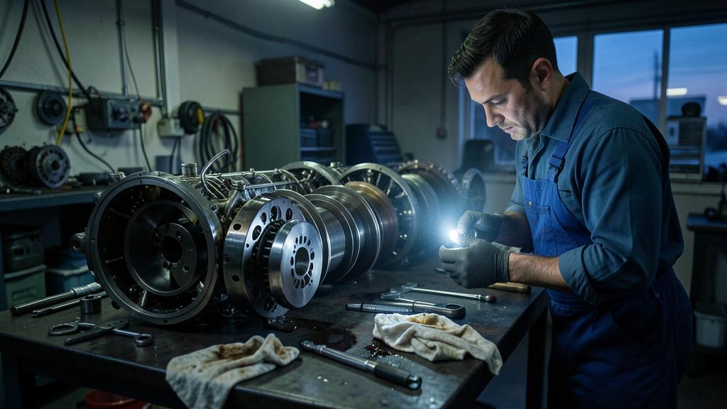
This is the reason a shop visit is a financial exercise as much as a technical one. Every disc opened up is an opportunity to replace one approaching the end of its life, and every disc not replaced will force the engine back into the shop when it gets there. The workscope question is therefore not “what is broken” but “what build will keep this engine on wing for the interval we are targeting, at the lowest total cost, given the lives remaining in the parts we will have exposed”.
| Input | Source | How it drives the build |
|---|---|---|
| Remaining cycles on exposed life-limited parts | Individual part records held under the continuing airworthiness organisation | Sets the maximum interval the engine can be built to |
| Condition found on strip and on borescope | The shop’s own findings, against the maintenance manual limits | Determines the mandatory content of the visit |
| Target time on wing | The operator’s fleet plan and route structure | Decides how much discretionary restoration is bought |
| Service bulletins and airworthiness directives | The engine manufacturer and the authority | Adds required or elective content while the module is open |
| Green time available elsewhere in the fleet | Fleet-level planning | May justify a lighter visit now and a heavier one later |
The right reflex. When a module is opened, list the life-limited parts that will be exposed and their remaining cycles before deciding the workscope, not after. A disc left in place with a short remaining life converts a planned visit into an unplanned one, and the second visit costs the disassembly all over again.
What this means for tooling, stands and people
Engine overhaul is a tooling-intensive activity, and the tooling is architecture-specific. Build stands, module handling fixtures, bearing compartment tools, blade and vane extraction tools, balance machines and their arbors are qualified for a particular engine family. A shop that adds a new family does not simply add labour; it adds a capital programme, a set of approvals and a training pipeline.
The human side matters as much. A technician’s competence on an engine family is specific, recorded and maintained under the approved organisation’s system, and the depth of that competence is what turns an architectural constraint into a routine morning rather than a problem. A shop that has built the same family for years develops sequences, checks and shortcuts that no manual contains, and losing that team costs more than losing a machine.
Reading the architecture back from the shop floor
Ask why a spool exists, and the answer comes from the compressor map. Ask why a bearing compartment is where it is, and the answer comes from the shaft it supports. Ask why a module comes out third rather than first, and the answer comes from what runs through it. The chain is short and it runs one way: aerodynamics decides, mechanics accommodates, and the shop lives with the sequence.
That is why an argument about two shafts against three is rarely a useful argument in the abstract. The right question for an operator is not which architecture is superior but which one their shop, their tooling, their records system and their people are set up to support — and what the whole chain costs over the life of the fleet rather than at the point of purchase.


Leave a Reply
You must be logged in to post a comment.