
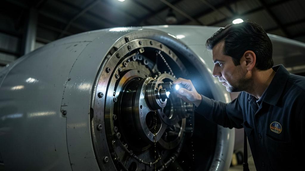
A reduction gearbox between the low-pressure turbine and the fan is an aerodynamic decision before it is a mechanical one. But the aerodynamics are fixed in the design stage, and what arrives in the shop is the mechanical consequence: a highly loaded gearbox, a lubrication system that is no longer an accessory, and a monitoring hierarchy where oil takes precedence over temperature. Nothing about this is new in aviation—it is just new at this performance level, on so many aircraft, in so many line stations.
Why the fan and turbine never wanted the same speed
The thrust efficiency improves when a larger mass of air is moved more slowly. That is the whole argument for high bypass ratios, and it points to a larger fan. But a larger fan cannot spin as fast: the tip speed is limited by transonic losses over the blade and by noise, both of which rise sharply once the tip becomes significantly supersonic. The larger the fan, the slower it must turn.
The low-pressure turbine that drives this fan wants exactly the opposite. The work of the turbine stage increases with the square of the blade speed; a turbine that must run slowly must recover the work through more stages, meaning more disks, more blades, more length, and more weight—and the low-pressure turbine is already one of the heaviest modules in the engine.
In a direct-drive architecture, a shaft speed must satisfy both requirements, and neither gets what it wants. Inserting a reduction gearbox breaks this constraint: the fan turns slowly, the low-pressure spool turns fast, and each is designed close to its own optimum. The turbine loses stages, the fan gains diameter, and the bypass ratio increases without the turbine weight following.
None of this is new in aviation. Turboprops have used reduction gearboxes from the start, and rotorcraft gearboxes have had much higher torque density for decades. What is new is the combination of this gearbox with a large civil turbofan, on short-haul aircraft that fly many cycles per day, maintained in a wide network of line stations. The engineering heritage exists; what has changed is the operational scale.
What actually sits between the shaft and the fan
The gearbox is a planetary gearset, and the chosen arrangement determines how it behaves. In a planetary configuration, the ring gear is held stationary, and the rotating carrier drives the output shaft, which turns in the same direction as the input shaft. In a star configuration, the carrier is held stationary, and the ring gear becomes the output shaft, which turns in the opposite direction to the input shaft. Both distribute the load across multiple gears rather than a single mesh, making a compact gearbox possible at all.
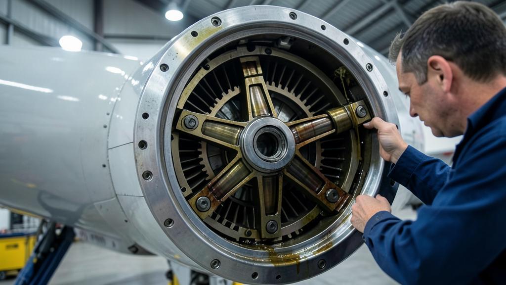
Two design details are more important for maintenance than the configuration itself.
The first is what the gears run on. At this load and size, plain bearings instead of rolling elements are the natural choice, and that is what has entered service in this power range: they carry enormous specific loads in very little radial space and have no rolling contacts that can spall. The compromise is absolute. A plain bearing has no dry-run tolerance—its load capacity is the oil film. Cut off the supply, and there is no intermediate state between functioning and destroyed.
The second is efficiency, and that is the number people get wrong in the wrong direction. A well-designed planetary gearset of this type is very efficient, but the shaft powers of a large turbofan are in the range of several megawatts at takeoff. A loss in the order of one percent is therefore a heat load in the range of several hundred kilowatts, all of it dumped into the oil, all of it that must be removed from the engine through the paths the engine already had: fuel and air. The gearbox needs not just lubrication. It needs a thermal management system that happens to also lubricate.
The gearbox is a critical part that must always be properly lubricated. If the oil stops flowing, the gearbox fails immediately. Also, the gearbox generates a lot of heat, so the oil system must also act as a cooling system.
On an Airbus A320neo with a PW1100G engine, the fan drive gearbox reduces the speed from the low-pressure turbine to the fan. At takeoff, the gearbox handles around 10 megawatts of power, with a 1% loss meaning 100 kilowatts of heat that must be managed by the oil system.
| Constraint | Direct-drive architecture | Geared architecture | Maintenance consequence |
|---|---|---|---|
| Fan speed | Coupled to the low-pressure spool; limits fan diameter | Independently set by the gear ratio | Larger, slower fan; different balancing and blade handling practices |
| Low-pressure turbine | Many stages to extract work at low speed | Fewer stages at higher speed | Less turbine hardware to inspect and replace during overhaul |
| Oil system task | Bearing support and chamber temperature | Bearing support plus large, continuous gearbox heat load | Larger oil volume, larger heat exchanger capacity, oil condition becomes safety-critical |
| Dominant new failure path | Bearing load, seal wear | Gear and plain bearing load, lubrication interruption | Debris and oil monitoring move to the top of priorities |
| Vibration content | Shaft orders dominate | Shaft orders plus gear mesh frequencies and sidebands | Balancing instrumentation alone no longer covers the spectrum |
| Shop capability | Established modular network | Gearbox as a separate module with dedicated tooling and cleanliness standards | Fewer qualified facilities; the throughput becomes a planning variable |
The oil stops being a consumable
In a conventional engine, oil is something you maintain, loosely monitor for consumption, and change or remove on program. In a geared architecture, the oil is a load-bearing element of the machine. Everything follows from that.
Oil quality and approval stop being interchangeable in practice, even if they are nominally approved alternatives. Manufacturers set restrictions on mixing brands and using approved oils, and these restrictions exist because the additive chemistry and thermal behavior differ. The dangerous property of the wrong oil is that it is invisible: the level is correct, the maintenance was recorded, the aircraft departs, and nothing indicates anything until the consequence is expensive.
The contamination discipline changes for the same reason. A gearbox generates both debris and is destroyed by it. Anything introduced during maintenance circulates, and the filter is the only thing between it and a plain bearing. That is why the everyday parts of line practice—clean funnels, sealed containers, correct part numbers, no improvised top-ups—stop being housekeeping and become airworthiness.
And the oil consumption itself becomes an instrument. The rate at which an engine consumes oil is one of the oldest health indicators in the business, but in a geared engine, a sudden change in that rate is a first sign, not a curiosity. It only works if the maintenance records are honest and complete—quantity added, date, engine hours—which puts the value of the entire indicator in the hands of whoever fills out the form at 2 a.m.
The right reflex. Record every oil top-up with quantity and engine time, even if it is small and even if no one asks. The consumption trend is only as good as the worst-kept record in the series, and it is often the first thing to move.
Debris monitoring takes precedence over temperature
The classic health indicator of a turbofan on the aircraft is the exhaust gas temperature margin. It works because core degradation is gradual, cumulative, and thermally visible: the engine must work harder for the same thrust, and the temperature tells you. It is an excellent trailing indicator of a slow process.
Gearbox and plain bearing load do not behave the same way. It is local, mechanical, and can develop from detectable to consequential without moving a single gas path parameter. Nothing in the core temperatures will tell you that a gear tooth is starting to break. What will tell you is what the oil carries.
This shifts the monitoring hierarchy. Oil-borne debris detection becomes the leading indicator, and the gas path becomes confirmation of something else. It also means that the oil monitoring techniques are not redundant to each other—they see different particle populations, and using only one leaves a gap.
| Method | What it detects | What it misses | Latency |
|---|---|---|---|
| Magnetic chip detector | Ferromagnetic particles large enough to be magnetically captured; presence and quantity | Non-ferromagnetic debris; fine wear below capture size | Found at inspection, so as good as the inspection interval |
| Electrical or quantitative debris monitor | Particle events in real time, with counting and sizing | Non-conductive or very fine debris, depending on the measurement principle | Continuous; can generate an in-service alert |
| Filter debris analysis | The entire captured population, including particle size and morphology | Everything that passed the filter or deposited upstream | Filter removal plus lab time |
| Spectrometric oil analysis | Dissolved metals and very fine particles; slow, distributed wear trend | Increasingly insensitive to larger particles—exactly what a breaking tooth produces | Sampling plus lab turnaround time |
| Oil consumption trend | Changes in leakage or seal behavior | Anything that does not affect the mass balance | Only as timely as the maintenance records |
The morphology point deserves special mention because it is the part most often discarded. Wear debris is not simply present or absent: fine rubbing wear, fatigue spalls, and cutting wear produce different particle shapes and size distributions, and a lab that reads a filter or a detector inlet deposit can distinguish normal run-in from something progressive. This distinction exists only if the debris survives to be examined.
The trap. Cleaning a magnetic chip detector, reinstalling it, and returning the aircraft to service destroys the only physical evidence of what is happening in the gearbox. The particle itself—its size, shape, and quantity—is the diagnosis. Handling and preserving the deposit per the manual is not paperwork; it is the difference between a trend and a guess.
A new set of frequencies
The vibration monitoring of the engine in a conventional turbofan is dominated by shaft orders. The balancing targets the fan’s own rotational frequency, and the instrumentation and analysis are built around it.
A gear mesh generates excitation at the mesh frequency—the number of teeth multiplied by the rotational speed of the meshing elements relative to each other, which in a planetary gearset means relative to the carrier and not the engine case. It is well above the shaft orders, with sidebands spaced at rotational frequency when the mesh is modulated by an eccentricity or a damaged tooth. This signature is where the gearbox condition lives, and the standard balancing equipment is neither sensitive to it nor tuned for it.
The practical consequence is not that every line station needs a spectrum analyzer. It is that a normal fan balancing result is not evidence that the gearbox is healthy, and a vibration complaint on a geared engine cannot be closed by balancing alone unless the manual says so.
The shop visit is not the shop visit you knew
A gearbox system is not a line-repairable part in any meaningful sense. It is a module, and the module goes to a facility with the tooling, the cleanliness standard, and the metrology to work on it: gear contact pattern and backlash checks, inspection of the tooth flanks and bearing surfaces to defined criteria, torque and assembly sequences with no field workaround.
Two planning consequences follow. First, the number of qualified facilities at the start of the program’s life is small, and the throughput is a real variable and not a contractual assumption—that is important for anyone building a spare engine pool or negotiating a maintenance agreement. Second, the work scope logic changes: the low-pressure turbine carries less hardware than its direct-drive equivalent, so some traditional overhaul content shrinks while a new, specialized content appears. The total amount is not obviously higher or lower; it is differently distributed, and the distribution shifts as fleet experience accumulates and the maintenance program is revised.
What has not changed, and a lesson from entry into service
It would be a mistake to conclude that a geared engine is a gearbox with an engine bolted on. The core is still the core. High-pressure turbine blade and nozzle loading, seal wear, clearances, and the gradual erosion of the exhaust gas temperature margin remain the dominant degradation mechanisms and still drive most removals. Life-limited parts are still counted in cycles and still determine shop visit scheduling in high-cycle operations.
Entry into service delivered a useful reminder. The largest publicly reported fleet disruption in a geared turbofan program to date arose from contamination in the powder metal used for high-pressure rotor parts, requiring accelerated inspections across a large fleet. It had nothing to do with the gearbox system. The architecture that drew all the technical attention was not the one that grounded the aircraft—a good argument for keeping the whole engine in view and not just the novel part of it.
What the line must do differently
For line and base maintenance, the changes are concrete and mostly unspectacular.
- Treat oil maintenance as a controlled process: correct approved oil grade, no mixing outside what the manual allows, clean equipment, complete recording of quantity and engine time.
- Treat magnetic chip detector and filter findings as evidence. Preserve the deposit, follow the manual’s procedure, and never clean and install outside the defined procedure.
- Maintain the sample logistics as a real process with its own turnaround time—a sample that sits in a cupboard for a week is a monitoring gap, not a monitoring program.
- Preserve trend continuity across module and engine changes so the hardware history follows and not the aircraft tail number.
- Treat oil system messages and indications on their own merits, not as a variant of “top up and go.”
The underlying shift is one of mindset and not technology. A geared architecture rewards operators who continuously monitor a slow, quiet parameter and react to small changes, and punishes those who wait for something to show in the gas path. That is a skill in itself, and it is starting to appear in Engine and propulsion roles as an explicit requirement and not an assumption.


Leave a Reply
You must be logged in to post a comment.