
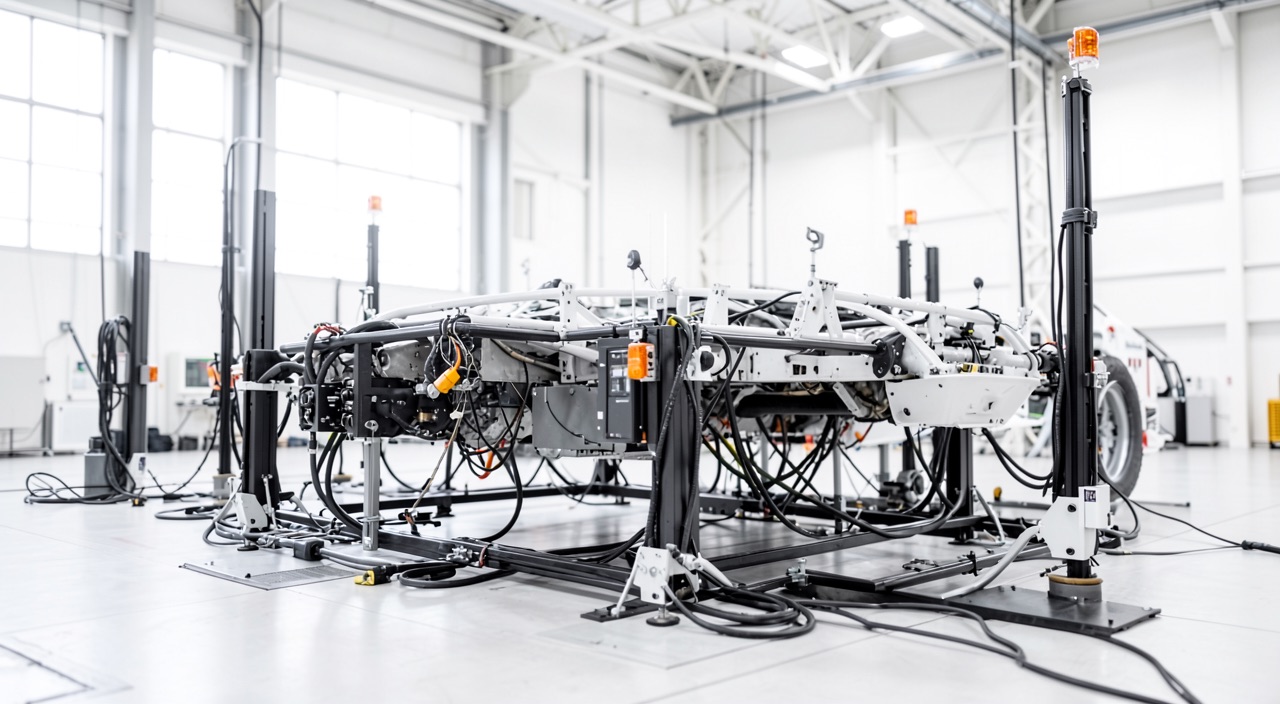
A center wing box inspection task appears in the maintenance program, with a threshold and an interval expressed in cycles. Where do these two numbers come from? Neither from the maintenance manual nor from an arbitrary margin: from a bare airframe, strapped down in a test hall, fatigued day and night for years by hydraulic actuators — and which must, at every moment, have lived through far more than the oldest aircraft in the fleet.
A bare airframe, actuators, and a load spectrum
The fatigue test article is not an aircraft. It is a complete primary structure — wing, fuselage, empennages, pylons, simulated landing gear — with no furnishings, no operational systems, bristling with strain gauges and connected to dozens of actuators through whiffletrees that spread the load over pads bonded to the skin. A servo-control system applies, channel by channel, a load sequence that reproduces not an average flight, but the mix of missions the manufacturer has chosen as representative of future use: taxi, rotation, climb, gusts and cruise maneuvers, descent, landing impact, braking, and above all, for a fuselage, the pressurization cycle that dominates everything else.
This spectrum is not raw reality. It is shaped, and every one of these adjustments is justified in the file. The smallest loads are truncated: they do not grow a crack and would cost months of bench time. The rarest loads are clipped, not to save time but to stay conservative — an isolated overload delays crack propagation by creating a plastic zone at the notch tip, and a test that included every overload of real life would give a flattering, unrealistic life. Marker loads are inserted at known intervals: they print readable striations on the fracture surface that will, years later, allow the onset to be dated under a microscope.
The rig runs continuously. Where an airliner accumulates a few cycles per day, the installation typically runs through several per hour, without interruption. It is this difference in pace that drives the whole affair: the rig can build a lead, and it is not allowed to lose it.
The test airframe is pushed harder and faster than any real plane to find problems before they happen in service. It’s like a time machine for metal fatigue, showing where cracks will start years before they would in actual flights.
An Airbus A320 test airframe might run through 10,000 pressurization cycles in 2 years (5 cycles/day → 10,000 cycles in 2,000 days), while a real A320 in short-haul service might take 10 years to reach the same number (1 cycle/day → 10,000 cycles in 3,650 days). The test rig reaches the same fatigue state 5x faster.
The pyramid: why the full airframe cannot be replaced
Fatigue substantiation is organized in tiers. At the base, hundreds or even thousands of coupon specimens give what nothing else can: statistics. The fatigue life of a material and an assembly is not a single number, it is a wide distribution, and it takes many cheap tests to learn its shape. Above that come elements — stiffeners, splices, fittings, bolted joints — then sub-assemblies: a wing box, an engine pylon, an empennage attachment.
At the top, a single article. It is expensive, it is unique, and it delivers what no calculation can guarantee: the real load paths. Secondary bending in a splice, load transfer after an element fails, the actual play in fasteners, assembly stresses frozen in during build, the effect of a cutout nobody paid attention to — none of this appears except at full scale. Industry experience points the same way every time: the first crack on the rig rarely appears where the calculation expected it, and the whole merit of the test is to show it before the fleet does.
The test does not stop when someone decides to stop it. It ends with a residual strength demonstration on the cracked structure, then with destructive teardown. This teardown is the real harvest: sensitive areas are cut out, joints are opened, fracture surfaces are read. Cracks are found far below the detection threshold of a line inspection — cracks nobody suspected existed, and which decide everything else.
Lead over the fleet: the only variable that matters
A fatigue test generally starts before the type enters service and continues long after. As long as the rig’s counter stays well above that of the oldest aircraft, every finding turns into a corrective action — a modification, a service bulletin, a new inspection task — before a single aircraft reaches the affected zone. The manufacturer is then working in the future of its own fleet.
When the lead shrinks, the relationship reverses. All that remains is extrapolation, that is, the assumption that nothing new will appear in a range nobody has ever traveled. This is exactly the assumption that the history of aircraft structures has disproved more than once. Hence the classic responses: extend the test beyond its initially planned duration, launch a second article, or resume an already partially consumed article to go further.
This lead has a documentary translation: the structural program carries a limit of validity, beyond which it is no longer demonstrated that the planned inspections are sufficient. This limit exists mainly because of a mechanism that ordinary inspection cannot catch — widespread fatigue damage. It is no longer a single crack that is found and repaired, but a population of small cracks spread over many sites or many elements, each below the detection threshold, which together destroy the built-in safety assumption: the structure no longer carries the load after an element fails, because the neighboring elements are already damaged. Only teardown of the rig, with its fractographic examinations, can date its onset.
The scatter factor, or the price of a single article
The rig gives a number: the life reached by that particular airframe, built from that batch of material, assembled by that team, subjected to that spectrum. The fleet, meanwhile, will often number in the hundreds: other material batches, other assembly tolerances, other operating patterns. Publishing the rig’s life as a limit would mean confusing a single draw with the law that produced it.
This is the role of the scatter factor: to divide the demonstrated life to bring the result back into the lower part of the distribution. Its value is not universal. It depends on the philosophy adopted, the amount of coupon test data available, the number of articles tested, and the confidence placed in the spectrum. An inspection threshold derived from a test is obtained by dividing the demonstrated life by a modest factor — on the order of a few units — without this figure having the value of a general rule; a declared safe life, with no inspection to catch the error, requires substantially more. Remember the principle rather than the number: the more unrecoverable the consequence of an underestimate, the larger the divisor.
The right reflex. When a structural life figure circulates, always ask which side of the factor it sits on: life demonstrated on the rig, or life published after division? The two look alike in a presentation and differ by a factor that changes the whole argument.
From the rig to the manual: thresholds, intervals, and life limits
Two philosophies coexist, and they do not lead to the same type of line in the documentation. In damage tolerance, one postulates that a crack already exists, demonstrates that it grows slowly and is detectable long before becoming critical. The first inspection threshold comes from the time needed to reach detectable size; the interval comes from the window between detectable and critical, divided so that several visits fall within it.

In safe life, the inspection is not credited: either because the part is not accessible, or because the crack grows there too fast for a visit to have a chance of seeing it, or because its failure leaves no load path. The part comes out at the life limit regardless of its apparent condition. This is the regime for landing gear, many fittings, and critical rotating engine parts.
| Criterion | Damage tolerance | Safe life |
|---|---|---|
| Starting assumption | A defect already exists in the part | The part is sound until removal |
| What the test must provide | Crack growth laws, critical size, residual strength | Life to initiation, associated dispersion |
| Effect of the scatter factor | On the inspection threshold and interval | On the published life, in one step |
| Documentary translation | Structural inspection tasks, some carrying limitation status | Life-limited part, mandatory removal |
| Operator’s room to maneuver | None on an airworthiness limitation; possible on a task from the recommended program alone | None; the counter is final |
| What happens when exceeded | The detectability demonstration collapses: the structure is no longer covered | Part not airworthy, no discussion possible |
Where this lands matters as much as the calculation itself. Tasks derived from the fatigue and damage tolerance demonstration move up into the airworthiness limitations section of the instructions for continued airworthiness: these are obligations, not recommendations. They do not shift because a grounding is inconvenient, and an escalation that is legitimate for a system task is not legitimate for a structural limitation without dedicated approval.
The trap. A major repair or a separately approved modification falls outside the domain covered by the test article: it locally changes stiffness, and therefore the load path and the spectrum seen by the adjacent structure. Its file then carries its own inspection program, with its own thresholds. This is the annex most often lost during a change of operator or a registration transfer — the aircraft flies compliant with the type’s maintenance program, but not compliant with its own configuration.
What the rig does not see
A test article is new, clean, and dry. It knows neither the filiform corrosion under aged paint, nor the condensed water pooling at the low point of a hold, nor the catering cart that struck a frame, nor the repair made one evening at a stopover. These mechanisms are not refinements: they interact with fatigue, a corrosion pit being an excellent initiation site. The maintenance program handles them through other channels — a corrosion prevention and control program, accidental damage treatment, repair assessment — precisely because the test does not cover them.
What remains is the most insidious gap: usage. The design spectrum assumes a mix of missions. An operator that flies a string of short sectors consumes cycles much faster than hours, while long-haul operation does the opposite. Two airframes of the same type with the same number of hours can sit at very different points in their fatigue life.
| Gap | Why the test does not cover it | Addressed by |
|---|---|---|
| Material and assembly variability | Only one article tested | Scatter factor |
| Corrosion and aging | New article, hangar environment | Corrosion prevention and control program |
| Accidental damage | Random events, not simulable | Assessment and repair criteria |
| Repairs and modifications | Configuration different from the article | Damage tolerance evaluation specific to the file |
| Usage more severe than assumed | Spectrum frozen at design | In-service monitoring, fleet leader aircraft |
| Multi-site cracking | Invisible without teardown | Destructive teardown and limit of validity |
The right reflex. Once a year, compare the actual cycles-to-hours ratio of your airframes to the one assumed in the type’s certification file. If your operation is drifting toward shorter sectors, it will not be the hour-based limit that catches up with you, and your structural milestones will arrive earlier than budgeted.
What to check in your own documentation
Three checks can be done without waiting for an audit. First, know how to trace, for a given structural task, its source: airworthiness limitation, recommended program task, or requirement stemming from an airworthiness directive. The regime for changing it is not the same, and the most common error is to treat all three as a single category in the tracking system.
Next, place the oldest airframe relative to the structural program’s limit of validity, in both cycles and hours, and know the real lead time for processing an extension. An extension rests on additional tests and analyses: it is not obtained within a quarter. The useful question is not whether the fleet is in compliance today, but on what date it stops being so if no file moves forward in the meantime.
Finally, the blind spot: repairs. Every repair classified beyond a certain threshold must be linked, in the aircraft’s records, to its own inspection program. On a used aircraft, this link is the first thing to reconstruct — and the most expensive to piece back together after the fact. For anyone preparing a certifying staff qualification or a role in continued airworthiness management, knowing how to trace the chain from test, to factor, to limitation, to task is worth more than remembering numbers: the numbers change from type to type, the reasoning never does. Field discussions on reconstructing these records take place regularly on the FL330 forum, and the continued airworthiness course offered at formations.fl330.com works through this chain document by document.
This article describes a general mechanism. For a given type, the applicable certification specifications, the airworthiness limitations published by the type certificate holder, and the operator’s approved documentation always prevail over what is written here.
Questions fréquentes
Why must the fatigue test stay ahead of the fleet?
Because a finding only has preventive value if it occurs before the first aircraft reaches the affected zone. As long as the rig has lived through far more than the oldest airframe, every crack found turns into a timely modification or inspection. Once the lead runs out, all that remains is extrapolation into a range nobody has traveled — and that is exactly where the history of structures has produced its worst surprises.
What exactly does the scatter factor do?
It corrects for the sample size, not for uncertainty in the loads. The rig provides the life of a single airframe, made from one batch of material and one assembly, whereas the fleet will number in the hundreds, with fatigue life spread across a wide distribution. Dividing the demonstrated life brings the result back into the lower part of that distribution. The divisor grows larger the less any inspection will be there to catch an underestimate.
Can a structural inspection task be rescheduled like a system task?
Not when it comes from the airworthiness limitations section: it is an obligation whose deadline conditions the validity of the safety demonstration, and changing it requires dedicated approval. A task that comes solely from the recommended maintenance program, on the other hand, can evolve through the operator’s program approval process. The first check is therefore to identify the task’s source in the tracking system before proposing any escalation.
What happens as the structural program's limit of validity approaches?
Beyond this limit, it is no longer demonstrated that the planned inspections are sufficient to cover multi-site cracking, and the aircraft can no longer be operated on that basis. Extending the limit requires additional tests and analyses on the manufacturer’s side, then approval: the timeline is counted in years, not quarters. An operator must therefore know the date on which its oldest airframe will reach this limit, not just its status today.
Have two aircraft of the same type with the same hours consumed the same amount of fatigue?
No, and the gap can be considerable. The design spectrum assumes a mix of missions, whereas real-world usage makes the ratio of cycles to hours vary widely. An operation flying short sectors accumulates pressurization cycles and landing impacts much faster than a long-haul operation at the same number of flight hours. In that case, it is the cycle-based limit that will bite first.
Is a major repair covered by the type's inspection program?
Not automatically. A repair locally changes stiffness and therefore the load path, which alters the spectrum seen by the adjacent structure: the test article never saw that configuration. For this reason, the repair file carries its own evaluation and, where applicable, its own inspection thresholds and intervals. This annex must follow the aircraft in its records, particularly during a change of operator.


Leave a Reply
You must be logged in to post a comment.