
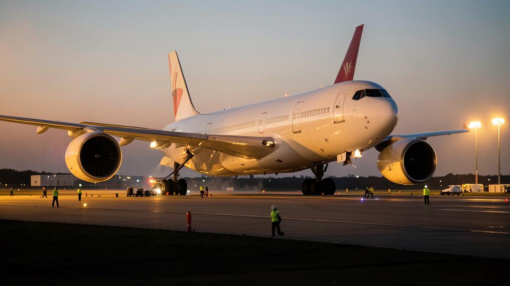
Increasing the bypass ratio is the most reliable way to reduce the fuel consumption of a turbofan, and the industry has been doing so for sixty years. What the marketing figure rarely says is that the gain is made in the engine and the bill is paid by the aircraft: in the nacelle drag, in the structural mass, in the length of the landing gear, and in the size of the tail. Here is the physics that makes the fan grow, and where the money comes back out.
Why a larger fan is worth having
Thrust is a change in momentum. An engine produces it by taking a mass of air and accelerating it: the force is the mass flow multiplied by the increase in speed. That leaves an infinity of ways to make the same thrust: a small mass thrown very fast, or a large mass moved gently.
The two are not equivalent, because the energy left in the jet is wasted. In the ideal momentum model, the propulsive efficiency is 2 / (1 + Vj/V0), where Vj is the jet velocity and V0 the flight speed. As the jet velocity approaches the flight speed, the efficiency approaches unity — and the thrust approaches zero. The practical design point is, therefore, always a compromise: moving as much air as the installation will tolerate and accelerating it as little as the thrust requirement allows.
The bypass ratio is the number that expresses the compromise. It is the ratio between the mass flow that passes around the core and the mass flow that passes through it. A pure turbojet has a bypass ratio of zero, and its jet velocity is enormous. The first generation of civil turbofans was well below two. The narrow-body engines that entered service in the 1980s were around five. The current generation of narrow-body engines ranges between nine and twelve, depending on the architecture, and the largest fans in service now approach the diameter of the fuselage of a narrow-body aircraft.
Two clarifications matter before proceeding. First, the bypass ratio moves propulsive efficiency. The other half of the specific fuel consumption is thermal efficiency, which lives in the core and is bought with the total pressure ratio, the turbine entry temperature, and the materials. A high-bypass engine with a mediocre core is not an efficient engine. Second, the reduction in jet velocity is also what makes modern engines quiet: jet mixing noise scales very sharply with jet velocity, which explains why the ICAO Annex 16 noise certification standards and fuel figures moved in the same direction for a generation without anyone having to choose between them.
A larger fan moves more air at lower speed, which saves fuel but makes the engine bigger and heavier. The aircraft pays for this with extra drag, stronger structure, and sometimes even redesigns to fit the bigger engine.
The CFM LEAP-1B engine (bypass ratio ~9) on a Boeing 737 MAX has a fan diameter of 69 inches. This requires careful ground clearance management: the engine was mounted higher and further forward, and the nose landing gear was lengthened to accommodate it, adding weight and complexity.
The nacelle bill: wetted area and interference
A larger fan needs a larger nacelle, and a nacelle is not free. It has an external surface over which the air rubs, and its drag scales roughly with that wetted area. It also has an inlet whose length is determined by the acoustic lining requirements and the quality of the inlet flow, a fan cowl, and a thrust reverser whose structure is sized by the loads it must withstand.
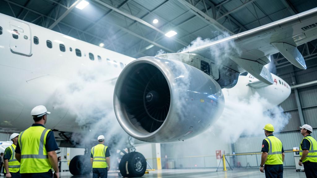
Worse, the nacelle is not in clean air. Under a wing, it interacts with the pylon and with the wing’s own pressure field. That interference is a genuine drag element, changes with angle of attack, and is one of the reasons why a re-engined aircraft requires wind tunnel and flight tests that have nothing to do with the performance of the engine itself. The nacelle strakes — the small fins on the sides of many nacelles — exist to shape the vortex that the nacelle sheds at high angle of attack, so that the flow over the wing behind it is helped rather than spoiled. They are a solution to an installation problem that the engine did not have on the test bed.
This is the first and largest reason to be suspicious of an unadorned specific fuel consumption improvement. An uninstalled figure measured in a test cell does not include the nacelle drag, the interference drag, the bleed and power extractions that the aircraft demands, nor the installation inlet losses.
| Consequence | Direction | Mechanism | Paid by |
|---|---|---|---|
| Propulsive efficiency | Improvement | More mass flow at lower jet velocity for the same thrust | The engine — this is the main point |
| Jet noise | Improvement | Jet mixing noise falls sharply with jet velocity | The engine, although fan noise partly replaces it |
| Nacelle drag | Worsens | Wetted area and interference grow with diameter | The aircraft structure, in every sector |
| Propulsion system mass | Worsens | Fan, disk, containment case, nacelle, reverser, pylon, all scale | The aircraft structure, and the payload it gives up |
| Ground clearance | Worsens | The diameter grows downward in a low-wing configuration | Landing gear, or the shape of the nacelle, or the whole configuration |
| Windmilling drag and yaw with an engine out | Worsens | Larger stopped or windmilling fan area | Tail, rudder, and the net flight path certified |
| Fan tip speed | Restricts | The tip Mach number increases with diameter at constant shaft speed | The low-pressure system architecture |
The mass bill, and where it is carried
Everything in the low-pressure system grows with the fan. The blades lengthen and weigh more; the disk that holds them grows to support the centrifugal load; the containment case that surrounds them is sized to keep a released blade inside the engine — a condition demonstrated by the blade-out test required for engine certification under European and U.S. engine codes, and one of the most brutal structural demands in aviation.
Beyond that, the nacelle structure, the acoustic panels, the thrust reverser, and the pylon also scale. Inside, the shaft and the low-pressure turbine that drives the fan also grow, for reasons covered in the next section. The result is that the propulsion system mass tends to increase faster than thrust in a re-engined aircraft, and the aircraft structure absorbs it: heavier wing loads, revised flutter margins, a pylon attachment reinforcement, sometimes a wing box reinforcement.
- Fuel savings are proportional to the time the engine runs
- The mass penalty is carried on every sector, including the short ones
- On a long-range mission, the trade is comfortably positive
- On a one-hour regional sector, the additional mass may consume a notable part of a headline improvement
The timing of the trade matters as much as its size. Fuel savings are proportional to the time the engine runs; the mass penalty is carried on every sector, including the short ones. On a long-range mission, the trade is comfortably positive. On a one-hour regional sector, the additional mass may consume a notable part of a headline improvement, which explains why the same engine family can seem transformative in one operator’s network and just good in another’s.
The tip speed problem, and why the gearbox appeared
A fan is a set of airfoils, and airfoils have a Mach number limit. The tip speed is the product of the radius and the rotational speed, so, at constant shaft speed, a larger fan drives its tips further into the transonic regime, where shock losses and noise increase. The fan must, therefore, rotate more slowly as it grows.
That creates a conflict, because the same shaft drives the low-pressure turbine, and turbines are efficient at high blade speed. Reducing the shaft speed to accommodate the fan makes the turbine work harder for less: the designer must add stages, increase the turbine’s mean radius, or accept a loss. Adding stages adds length, mass, and cost — and the added mass is in the rear of a component that already hangs from a pylon.
Two architectures respond to this. The first is to accept a large, multi-stage low-pressure turbine running at a compromise speed. The second is to insert a reduction gearbox between the turbine and the fan, allowing each to rotate near its own optimum speed: a fast, compact turbine with fewer stages, and a large, slow fan. The geared arrangement recovers stages and mass from the turbine, at the cost of the gearbox itself, the heat it rejects, a larger oil and cooling system, and a new critical component in the maintenance program. Both routes are in service and neither has proven universally superior — the answer depends on the thrust class, the mission, and the operator’s maintenance economics.
The trap. Comparing two engines only by the bypass ratio says almost nothing. A high bypass ratio achieved with a heavy, high-drag installation and a mediocre core may burn more fuel per seat-kilometer than a lower-bypass engine with an excellent core and a tight nacelle. The bypass ratio is a design parameter, not a figure of merit.
Ground clearance: the constraint that ends the argument
In a conventional low-wing aircraft with wing-mounted engines, the fan grows downward as much as upward. Ground clearance is a hard limit: it protects against foreign object ingestion, against contact during a crosswind landing or a rotation, and against the practices of ground crews moving under the wing. Aerodrome design standards set the geometry with which the aircraft must coexist on aprons and runways; the aircraft cannot negotiate.
Four structural solutions are available, and each of them is costly elsewhere.
| Solution | What it gives | What it costs |
|---|---|---|
| Lengthen the landing gear | Ground clearance without touching the nacelle or the wing | Landing gear mass, a larger wheel well, wing box rework, altered ground attitude, sometimes a longer nose gear too |
| Reconfigure the nacelle — flattened or non-circular lower lip | Ground clearance with the existing landing gear and wing | Inlet flow quality, distortion at high angle of attack, a small permanent aerodynamic penalty |
| Move the engine forward and up on the pylon | Ground clearance without lengthening the landing gear | Altered installed aerodynamics and pitch moment behavior, revised pylon loads, a longer and heavier pylon |
| Change the configuration — high wing, or tail-mounted engines | Ground clearance by design, without penalty on the engine | A clean-sheet aircraft; in aft mounts, tail structure mass and an aft center of gravity problem |
The first three are what re-engine programs really do, in combination, and each of them consumes part of the gain that the larger fan produced. The fourth is why fan growth stops being an incremental decision and becomes an aircraft program decision.
The engine-out case grows with the fan too
A failed engine is not a neutral object. A larger-diameter stopped or windmilling fan presents more blocked area and produces more drag, and that drag acts with a lever arm from the centerline. The yawing moment to be countered grows, which goes straight to the certification basis: minimum control speeds, tail and rudder sizing, and the net flight path on which takeoff performance is built.
The same applies in cruise. The descent performance after an engine failure depends on the drag of the failed engine as well as the thrust of the operating engine, which matters for extended operations planning in twins. A larger fan, therefore, has a cost that does not appear in any cruise fuel figure and only manifests in a limiting case calculation.
Diminishing returns, and where design is going
The decisive fact is the shape of the two curves. The propulsive efficiency expression flattens: as the jet velocity approaches the flight speed, each additional unit of bypass ratio buys less efficiency than the previous one. The penalties — nacelle wetted area, propulsion mass, landing gear length, tail size — do not flatten. They keep growing, some of them faster than linearly.
| Stage | What is lost | Typically cited? |
|---|---|---|
| Uninstalled to installed engine | Inlet losses, bleed and power extractions, exhaust system installation | Rarely |
| Installed engine to propulsion system | Nacelle wetted area drag, pylon and wing interference | Rarely |
| Propulsion system to aircraft structure | Structural mass to carry it: landing gear, pylon, wing rework, tail sizing | Sometimes, at the aircraft level |
| Aircraft structure to mission | Stage length, payload traded for mass, share of climb and descent in the flight | Only in specific operator studies |
| Mission to network | Utilization, maintenance cost per hour, dispatch reliability, spare engine policy | Almost never |
Two consequences follow. The first is that the optimum bypass ratio is an aircraft-level optimum, not an engine-level one, and is different for a regional jet, a single-aisle aircraft, and a long-range twin. The second is that, once the incremental gain has flattened, the industry has to look elsewhere: to the core, where the total pressure ratio and the turbine temperature still have margin; to shorter, thinner nacelles that reduce the installation penalty rather than the engine fuel flow; to open-rotor configurations that abandon the nacelle altogether and assume a different set of problems, in noise, in blade containment, and in installation; and, finally, to aircraft configurations that stop putting the engine under a low wing.
The correct reflex. When a fuel consumption improvement is cited, ask four questions before comparing anything: installed or uninstalled?, in what condition?, in what aircraft?, and over what stage length?. If the answer to the first is « uninstalled, » the number describes an engine on a test bed, not an aircraft on a route.
Reading the claim
None of this is an argument that high bypass ratio was a mistake. It has been one of the largest contributors to the reduction in fuel consumption of civil aviation since the 1960s, and delivered much of the noise reduction along with it. The point is narrower: the parameter is a means, the fan diameter it implies is an installation problem, and the installation problem is solved in the aircraft, not in the engine.
That is why the interesting question about a new propulsion system is never its bypass ratio. It is what the aircraft had to give up to accept it — landing gear length, wing rework, tail area, payload — and whether the mission the operator actually flies is long enough for the trade to close. Engineers and operators comparing those trades in fleets tend to reach very different conclusions depending on the stage length, and the argument is a regular one in the FL330 forums.


Leave a Reply
You must be logged in to post a comment.