
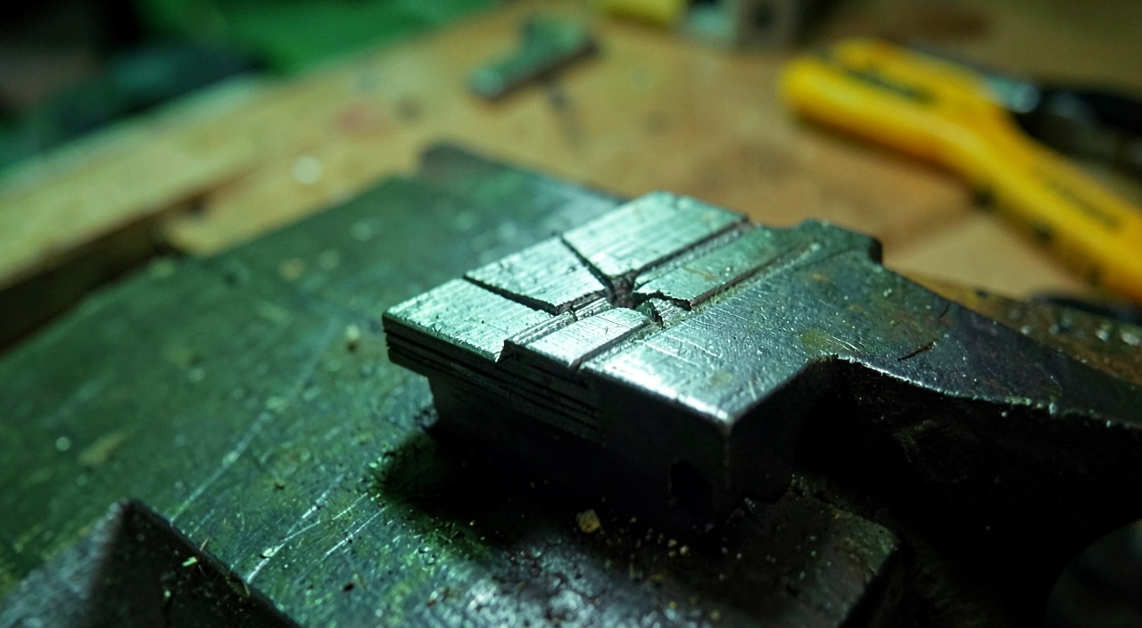
Two batches of the same fitting, printed on the same machine with the same powder, the same heat treatment, and the same design, are tested on a fatigue bench: the first meets its target, while the second initiates a crack much earlier. All dimensions are correct, the material is compliant, and the only difference lies in an angle—the part’s axis was laid flat on the platform for one batch, upright for the other. As long as this angle is not specified on the drawing with a reference, a value, and a tolerance, the definition is incomplete, just like a bore without a dimension.
The layer is a weld repeated thousands of times
Powder bed fusion does not cast a part: it welds it, layer by layer. Each pass of the beam creates a tiny molten pool that solidifies by bonding to the previously consolidated material. Heat is primarily dissipated downward, through the previous layers: the thermal gradient is, on average, aligned with the build direction. However, grains grow along this gradient, often through epitaxy on the lower layer, and growth continues from one layer to the next. The result is a columnar, textured microstructure, traversed by the boundaries of the molten pools—a material with a direction, like wood has a grain.
Heat treatments reduce this texture without necessarily eliminating it, and hot isostatic pressing closes voids without reorganizing the grains. The intuition inherited from casting must be reversed: the material is born at the same time as the geometry, and it is born oriented—physics of directional solidification, which is also found with different magnitudes in directed energy deposition.
To the anisotropy of sound material is added that of defects. A lack of fusion between two layers or between two adjacent beads has no reason to be spherical: it is flat, extended in the layer plane, bordered by sharp edges. The population of defects is therefore itself oriented—and it is this that governs fatigue.
Additive manufacturing builds parts layer by layer, creating a material with a grain-like structure. This structure is weaker in some directions, especially when forces pull across the layers rather than along them. Defects in the material are also oriented, making some parts more prone to cracking under stress.
A titanium bracket for an aircraft engine is printed with a build direction that aligns the layers parallel to the main stress direction. When tested, it withstands 50,000 cycles at 300 MPa before failing. The same bracket, printed with layers perpendicular to the stress, fails after only 5,000 cycles at the same stress level due to defects opening up along the layer boundaries.
In tension, the difference is debated; in fatigue, it is decisive
Static properties remain a subject of classic deratings: after appropriate heat treatment, yield strengths and resistances of different directions come closer together. Fatigue follows a different logic: life is not governed by the material’s average but by its weakest link—the most unfavorable defect in the stressed volume, or the most severe surface irregularity. A statistics of extremes, not averages.
Direct consequence: anything that orients the population of defects also orients fatigue resistance. At equal stress amplitude, specimens built upright—the load crossing the layers—initiate earlier than specimens built flat, and the scatter increases, since each life depends on the draw of its worst defect. On a fatigue curve, the difference is not read in points on the stress axis: it can be read in decades on the cycles axis.
The surface also plays a role. A raw part has a roughness that depends on the local inclination: surfaces in undercuts, built above supports, are notoriously more irregular than upper surfaces. The orientation therefore also decides where the most unfavorable skin will be located—and in a working area, this derating is compounded with that of the volume.
The defect does not change; it is the load that sees it differently
Why does the same defect weigh so differently depending on the direction of the load? Because in initiation, what matters is not the volume of the defect but its projected area perpendicular to the principal stress. A lack of fusion is a flat lens placed in the layer plane. Loaded in this plane, it presents to the stress only its thickness—a projection of the order of the layer thickness, a modest stress concentrator. Loaded perpendicular to the layers, the same defect exposes its entire extent: it behaves like a pre-existing crack the size of the lens.
Hot isostatic pressing changes this landscape without neutralizing it: it closes internal non-emerging voids, but does nothing for surface-connected defects or roughness. Machining removes the raw skin where the tool passes; an optimized topology part almost always retains inaccessible raw surfaces, and the interior retains its oriented population. No post-treatment makes a directional material isotropic: the gap is reduced, not decreed to disappear.
What a dimension actually does on a drawing
A dimension is not a number placed on a line; it is a complete system: a reference that indicates where to measure; a nominal value; a tolerance that bounds the acceptable; an agreed control method; a codified escape route when the result is out of bounds—retouch, waiver, scrap. Remove one element, and the dimension no longer protects anything: a tolerance without a reference is unverifiable, a control without a non-conformity path is a formality.
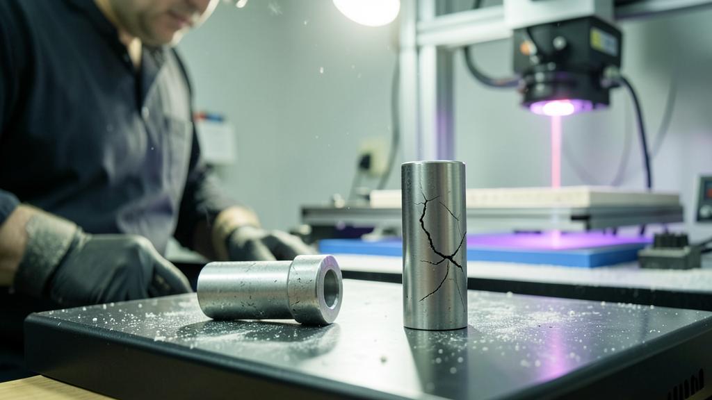
As soon as fatigue resistance depends on orientation, the build direction fills exactly the same boxes. The reference is the machine datum: platform plane, build axis, scan direction. The value is the part’s orientation in this datum—the joint additive manufacturing standards provide a designation of coordinate systems and orientations that removes all ambiguity. The tolerance is the allowed angular deviation, often zero in practice because the qualification was conducted for a precise implantation. Control and non-conformity are handled through the process and its witnesses—not by an instrument placed on the part.
| System element | For a dimension | For the build direction |
|---|---|---|
| Reference | Part datum system | Machine reference frame: build plate plane, build axis, scan direction |
| Valeur | Nominal | Angles between the part axes and the build axis, position on the plate if fixed |
| Tolerance | Tolerance band | Permitted angular deviation — often zero, since qualification was carried out for a precise layout |
| Inspection | Metrology on the part | Witness specimens from the build plate, process monitoring; metallography and CT scanning for investigation |
| Non-conformity | Rework, concession, scrap | Concession after fatigue strength analysis — never tacit acceptance |
Writing it on the drawing—and locking what surrounds it
In practice, the definition file specifies four things. The orientation itself: the part’s axes referenced to the build datum, with the allowed deviation. The frozen perimeter that accompanies it: position on the platform and lot implantation if the qualification is sensitive to it—the thermal history of a part depends on what melts around it. The support strategy and the surfaces left raw, which decide where the most unfavorable skins are located: working areas delivered raw are identified on the drawing, with their surface finish requirement. Finally, the reference to the process specification that locks parameters, powder, and post-treatments: the drawing carries the requirement, the specification carries the recipe.
The trap: a drawing silent on orientation is a drawing that authorizes all of them. The supplier who straightens a part to place more on the platform violates no requirement: each dimension remains good, the material certificate remains good, acceptance sees nothing—and the fatigue margin has changed without any document recording it. The deviation is undetectable precisely because there is no box where it should be written.
The qualification locks a set; orientation is part of it
Additive manufacturing falls under special processes in the sense of aeronautical quality references: the result cannot be entirely verified on the finished part—you do not measure a service life during acceptance. Confidence is built upstream: the material values used in calculations are only valid for the process window that produced them. Machine, fusion parameters, powder specification and reuse rules, implantation, orientation, heat treatments, finishing: it is this set that the qualification locks, and the directional deratings retained in calculations are inseparable from the qualified orientation.
Routine control relies on witness specimens built on the same platform as the parts, in representative orientations—including the critical loading direction, not just the most convenient to print. Their testing certifies that the day’s process remained within its window. Metallography can identify the build direction of a delivered part—the boundaries of molten pools do not lie—and tomography locates internal defects; but these are expert methods, not series controls.
The right reflex: treat any change in orientation as a change in definition, never as a workshop optimization. Go through the modification circuit, assess the fatigue impact with the calculation office, update the qualification before the first delivered part. And the first article file photographs the platform implantation, including orientation: it is the baseline for all future deviations.
What to go check in your own file
For those who design, purchase, or certify additively manufactured parts subjected to fatigue, the question arises in terms of audits and boils down to five points. Does the drawing or annotated model specify the orientation in a designated build datum, with a tolerance? Does the process specification lock the platform implantation, or only the parameters? Do the witness specimens cover the part’s critical direction, or only the vertical out of habit? Are working raw surfaces identified, with their own requirement? Does the modification circuit catch a change in implantation at the supplier, or does it go unnoticed?
Three gray areas remain, to be faced rather than discovered in service: the transfer to another machine of the same model, treated with varying re-demonstration requirements; local fusion repairs and repairs, singular thermal histories in an otherwise qualified part; the slow drift of parameters, which only regular witnesses can catch. The right answer is not universal: it is—or should be—in the qualification file of each organization, and its absence is the first finding of a well-conducted audit.
The applicable certification specifications, the standards called by the definition file, and the approved documentation of the design or production organization prevail, in all circumstances, over this article, which has only an informative value.


Leave a Reply
You must be logged in to post a comment.