
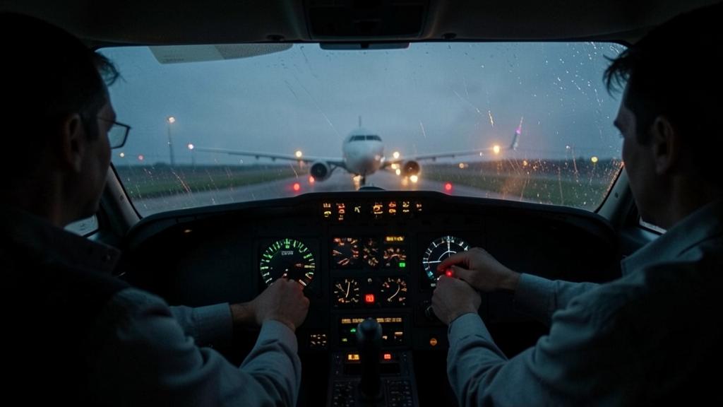
The reported wind on the ground is 220 degrees, 18 knots, gusts of 32. The displayed approach speed increases by approximately 15 knots, the runway is wet, and no one in the cockpit has recalculated the landing distance with this speed. The correction for gusts is one of the few decisions on final that improves one safety margin while degrading another, and the exchange is not symmetrical: what is gained in immediate protection is lost in energy to dissipate, and the repayment is made in meters of runway.
What the gust takes away and at what speed it takes it
A gust is not a force exerted on the aircraft: it is a variation in the speed of the air mass in which it is flying. The difference is not purely academic. The aircraft has considerable inertia, and its speed relative to the ground does not change much in a second; the speed of the air mass, however, can vary ten or fifteen knots in the same interval. Since flight speed is nothing more than the difference between the two, all the variation is immediately indicated on the airspeed indicator and, therefore, on the lift.
That is why a decrease in the headwind component is read on the airspeed indicator before the aircraft’s attitude has changed. The aircraft has done nothing; the air has gone. And since lift varies with the square of the speed, a decrease of fifteen knots from an approach speed of 140 knots takes away almost 20% in one go. At that point, either the angle of attack must be increased or sinking below the flight path accepted. The first term is deducted from the stall margin, the second from the remaining height: at 500 feet, both still exist, at 50 feet much less.
However, nothing at the crew’s disposal responds at that moment. In landing configuration, drag is high, and the engines are kept at a thrust setting that reduces acceleration time, but a few seconds are still needed between the power demand and the effective recovery of speed. During this delay, the only reserve available is the speed already acquired. That is the whole principle of gust correction: margin is not created when it is needed; it can only be bought in advance.
A gust reduces airspeed instantly, cutting lift. Since engines take time to react, pilots must add speed in advance to avoid stalling. This extra speed acts as a buffer against sudden drops.
An Airbus A320 on final at 140 knots with a 15-knot gust drop loses 20% lift. Adding 15 knots in advance keeps the margin safe, even if the gust hits at 50 feet.
From the speed margin to the load factor margin
Certification standards for large aircraft set the reference landing speed at least 1.23 times the reference stall speed in landing configuration. This 23% speed margin is the starting point for all reflection on gusts, but it is misleading when read in knots. What really protects is not the speed difference: it is the load factor that the wing can still support before stalling, and this varies with the square of the speed ratio.
At 1.23 times the reference stall speed, this factor is approximately 1.5 g. The maneuvering margin is therefore half a unit, in which the turn, the correction of a flight path deviation, and the vertical gust must fit. If the speed drops to 1.10 times the reference stall speed, which corresponds approximately to a decrease of 15 knots in a typical approach speed, only approximately 1.2 g remain. The margin read on the airspeed indicator has lost almost half of its real value, while the needle has only moved a tenth of the graduation. That is the real reason for the addition: it is not a matter of flying faster, but of not going down to the part of the curve where the margin collapses.
The vertical component of turbulence deserves separate treatment, as it does not act on the speed, but directly on the angle of attack. A 10-knot updraft, encountered at 140 knots, adds approximately four degrees of angle of attack, without the slightest delay and without anything being shown on the airspeed indicator. The lower the approach speed, the greater this induced angle of attack for the same vertical gust. The additional speed protects not only against the decrease in headwind, but also against the effect of vertical gusts, precisely those the angle-of-attack protection must handle as a last resort. It is the least mentioned argument in briefings and one of the most solid.
Two ways to create the same addition
Manufacturers have not adopted the same method, and a crew transitioning from one fleet to another must know which one applies. The first logic adds a fraction of the steady wind and all the difference between this steady wind and the reported gust, all limited to about 15 to 20 knots depending on the type. It explicitly attributes part to the expected gradient near the ground and part to the instantaneous event, which makes the removal on final understandable: each knot of the addition knows where it comes from, and when it should go.

A second logic retains a fraction of the headwind component measured in real time with a systematic minimum value and the same type of maximum value, and associates it with a ground speed servomechanism. The target flight speed is then continuously reconstructed: if the wind decreases during the descent, the command decreases accordingly, and the energy relative to the ground remains that which was aimed at since stabilization. The correction is withdrawn by itself, which is a considerable advantage and a surprise on the day when the autopilot is deactivated, as the pilot then inherits a task that the system was performing without saying so.
| Criterion | Fraction of the established wind + all the gust | Fraction of the headwind component, ground speed regulated |
|---|---|---|
| Input data | Reported, established, and gust wind at the time of calculation | Headwind component, permanently measured by the systems |
| Minimum value | Systematic minimum value of the addition, even with zero wind | Systematic minimum value of the addition, even with zero wind |
| Maximum value | Total value limited, of the order of fifteen to twenty knots | Total value limited in the same order, applied to the setpoint |
| Update in final | Fixed in the calculation, adjusted according to the crew’s judgment | Continuously recalculated by the system |
| Removal of the correction | Manual, by thrust management on final | Automatic, the setpoint decreases with the wind |
| What remains at contact | The part attributed to the gust | The energy relative to the ground, aimed at since stabilization |
| Own risk | Forgetting to remove, double counting of the margin | Dependence on wind measurement, surprise in manual flight |
What the two schools have in common is more instructive than what separates them. Both set a minimum value, since an approach without addition leaves very little reserve for the usual imprecision of pilots. Both set a maximum value, since beyond a certain threshold, the distance penalty exceeds the protection benefit: the additional speed is useless if it prevents stopping. And both start from an explicit decision on what remains at the moment of contact, a decision that neither the computer nor the checklist takes in place of the crew.
The price is paid in meters, and above all before contact
Kinetic energy varies with the square of the speed. Going from a reference speed of 140 knots to 155 knots means presenting almost a quarter more energy at the threshold. With the same braking capacity, the landing roll is extended in the same proportion: it is already a runway length that the tables do not give for free, especially on a wet or contaminated runway, where the braking coefficient is the limiting factor and the built-in margin is already reduced.
But the main problem is not there. The costly part is between the threshold and contact. As soon as you are in ground effect, with the engines reduced, the available deceleration does not exceed one to two knots per second: the aircraft only has its drag. At 140 knots, it covers approximately 72 meters per second. Each second of waiting for the speed to drop therefore consumes approximately the length of a large aircraft. Wanting to reduce ten knots in the air can therefore cost several hundred meters before the first brake has acted. That is why the appropriate reaction to an excessive speed at the threshold is almost always not to wait, but to touch down at the planned point and let the brakes do their work, or to perform a go-around.
| Size | Threshold at Vref (140 kt) | Threshold at Vref + 15 kt (155 kt) | Difference |
|---|---|---|---|
| Relationship with the reference stall speed | 1.23 VSR | approximately 1.36 VSR | + 0.13 |
| Available load factor before the stall | approximately 1.5 g | approximately 1.9 g | + 0.4 g |
| Kinetic energy relative to the air | Reference | approximately 1.23 times | + 23 % |
| Landing roll at identical deceleration | Reference | approximately 1.23 times | + 23 % |
| Ground speed at contact, if the headwind has dropped to 8 kt | 132 kt | 147 kt | + 15 kt |
The trap: the correction counted twice. It is integrated by the system in the target speed, then a few knots are added according to judgment, because there is turbulence, then the speed drifts upwards in the gusts, without being brought back. The aircraft arrives at the threshold 15 to 20 knots above the speed for which the landing distance was calculated, with an autobrake setting chosen for a shorter runway than the one that will actually be used. The flat-rate margin of the earlier calculation was never intended to cover an addition decided in flight: only the in-flight recalculation with the speed actually flown and the current runway condition answers the question asked.
Removing the correction: the maneuver that no one briefs
The correction is divided into two parts that do not have the same lifespan. The part attributed to the gust protects against an event that can occur at any time, even at 10 feet: it is kept until touchdown. The part attributed to the steady wind compensates for a gradient that weakens as the aircraft descends through the boundary layer. Keeping it until the end means increasing the ground speed by everything that surface friction takes away from the wind, without anything being shown: the airspeed indicator does not move.
That is exactly what a ground speed servomechanism does: it maintains the target energy relative to the ground and lets the flight speed target decrease if the wind weakens. In manual flight with manual thrust, the same result is obtained by hand, with a timely reduction. Too early, the aircraft goes below the flight path, when the margin is at its lowest; too late, it floats and the touchdown point moves further away. The approach briefing gains from naming this maneuver, as it does not appear on any checklist and yet decides where the aircraft lands.
The good reflex: announce a target ground speed at the threshold, not just a flight speed. The flight speed indicates what the wing feels; the ground speed indicates what the runway, brakes, and tires must absorb. Two figures are enough for the briefing: the target flight speed in stabilization and the expected ground speed at the threshold crossing, taking into account the wind likely to be present. A clear difference between this value and the one shown at 500 feet means that the wind is not behaving as expected, and it is exploitable information, long before the runway makes it evident.
Gust and wind shear: two phenomena, two reactions
The correction for gusts refers to a random fluctuation around an average wind, whose time scale is counted in seconds and whose characteristic is to return. Wind shear is another thing: a systematic modification of the average wind with altitude or position, which does not return and whose amplitude can far exceed any reasonable margin. No addition has ever been designed for wind shear; confusing them is an error of nature, not of degree.
The criterion that separates them is persistence. A loss of speed that resolves in a few seconds, with a vertical speed that remains within limits, and thrust that regains the upper hand, is a gust. A loss of speed that sets in, accompanied by a flight path deviation and an increasing need for thrust, is not, regardless of what the label on the observation report says. The procedure differs radically: in one case, the target is maintained and the flight control is allowed to work, in the other, the go-around procedure is applied, without waiting for the confirmation that is feared.
The second trap: the addition that delays detection. An increased approach speed offers a comfortable reserve, and this reserve is precisely the reason not to react immediately when the airspeed indicator starts to drop. The argument is obvious: the speed drops, but it is still clearly above the reference speed, so wait. The time thus gained is precisely the time that will be lacking if the event is a wind shear. The addition buys an energy margin, never a decision margin.
What you must verify in your own documentation
Seven points deserve to be found in black and white, rather than reconstructed from memory. The ceiling of the addition and what it includes. Whether the correction is already included in the speed shown by the system or is added to it. The behavior of the automatic approach compared with manual flight. What should remain at touchdown. The source of the wind used for the calculation, between the automatic observation, the ATC report, and the onboard measurement, which almost never coincide. The way in which the in-flight landing distance tables take into account an excess speed at the threshold. Finally, the way in which the demonstrated crosswind limit is expressed, in steady wind or in gust, since the answer influences the approach decision long before the speed changes.
There remains a gray area that the documentation will not fill. The wind on which the addition is based is an average value, measured on the ground, at a point that is not the threshold, and at a height that is not that of the wing. The correction protects against an instantaneous phenomenon based on a smoothed data point: it is a deliberate compromise, not a measurement. That is why what the crew feels on final has the last word over the calculated figure, in the direction of caution as well as in the direction of a go-around, and why an addition calculated in cruise is reconsidered at 1,000 feet.
For those preparing a type rating or an out-of-line check, two competencies regularly return and are rarely practiced: the calculation of the addition from the reported wind without assistance and the explanation of when and why the part attributed to the established wind is removed. The training resources FL330 detail these constructions by type, and the differences between the theory and what is observed in practice are discussed in the professional forum.
This article explains a mechanism; it does not replace an instruction. The applicable text, the flight manual of the type, and the approved documentation of the operator take precedence over all the above, even if the values they retain differ from those indicated here as orders of magnitude.


Leave a Reply
You must be logged in to post a comment.